Variable mass dynamic vibration absorber control method

A technology of dynamic vibration absorber and control method, which is applied in the direction of vibration suppression adjustment, spring/shock absorber, mechanical equipment, etc. It can solve the resonance of the main system, which has rarely been studied in depth, the effective vibration reduction bandwidth is narrow, and the vibration of the main system is increased. Large and other problems, to achieve the effect of broadening the effective vibration reduction frequency band, widening the effective frequency range, and broadening the vibration reduction frequency band

Inactive Publication Date: 2013-12-04
CHANGAN UNIV
View PDF5 Cites 22 Cited by
  • Summary
  • Abstract
  • Description
  • Claims
  • Application Information

AI Technical Summary

Problems solved by technology

However, its effective vibration reduction bandwidth is very narrow, once the tuning is lost, the vibration reduction effect will be significantly deteriorated
The second is that the installation of dynamic shock absorbers will cause new resonance peaks in the main system
However, when the traditional control method is adopted, the main system has a resonance peak at a place slightly less than 1rad / s, indicating that when the frequency of the exciting force changes, the main system still has the possibility of increased vibration due to resonance
[0014] It can be seen that most of the current research on dynamic vibration absorbers is focused on how to broaden the effective frequency band of the vibration absorber, that is, to solve the first shortcoming mentioned above, but how to solve the problem of resonance of the main system caused by the installation of the vibration absorber is very little. have done in-depth research

Method used


Image

  • Variable mass dynamic vibration absorber control method
  • Variable mass dynamic vibration absorber control method
  • Variable mass dynamic vibration absorber control method

Examples


Embodiment

[0061] Such as Figure 5 As shown, the main system is composed of a stainless steel cantilever beam and a vibration acceleration sensor at the end as the elastic element and mass element, and a spring steel sheet and a small glass bottle are used as the elastic element and variable mass unit respectively to form a variable mass dynamic shock absorber. The vibration absorber is installed at the end of the cantilever beam of the main system to form the experimental system. Use tap water as the variable mass medium. The main system is installed on the top of the electromagnetic exciter, and an acceleration sensor is installed on the bottom of the main system to measure the vibration signal input to the main system.

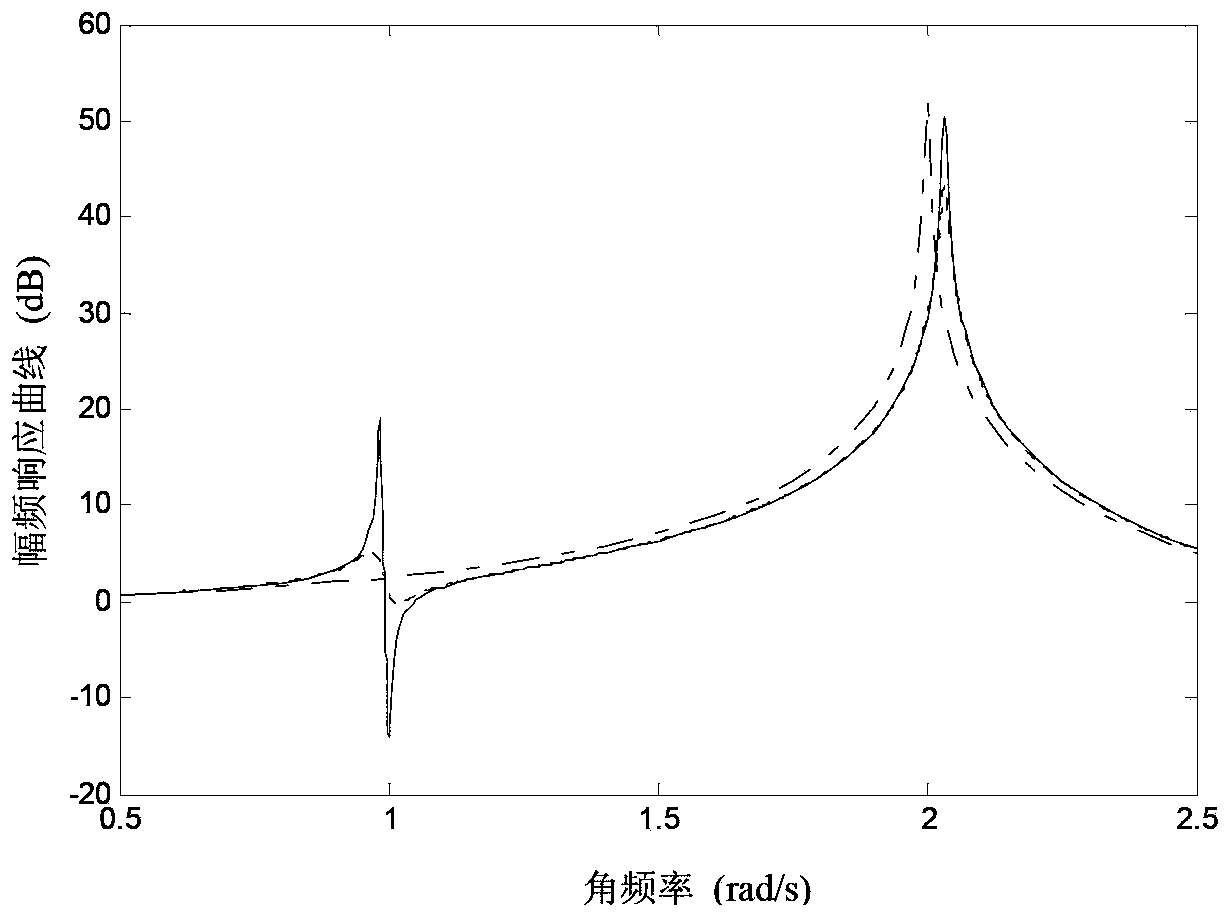
[0062] When the glass bottle is filled with water and not filled with water, the amplitude-frequency response curve of the main system is experimentally tested, such as Figure 6 shown. It can be seen that when the glass bottle is full, the vibration absorber redu...


PUM


Abstract

The invention discloses a variable mass dynamic vibration absorber control method. A sensor used for collecting main system input and output vibration signals is arranged on a compound system composed of a main system-variable mass dynamic vibration absorber, and when the minimum inherent frequency omega m and the maximum inherent frequency omega n of the variable mass dynamic vibration absorber are used respectively, an amplitude-frequency response curve of a main system in the frequency range (0,omega t] is formed; as for the variable mass dynamic vibration absorber control method, while the main system works, the main system vibration signals are collected through the vibration sensor, and excitation frequency omega exerted by the external world is calculated through fast Fourier transform; the variable mass dynamic vibration absorber is controlled according to the value of the excitation frequency omega. According to the variable mass dynamic vibration absorber control method, the effective vibration reduction frequency band of the vibration absorber can be effectively broadened, the phenomenon of resonance of the main system after the vibration absorber is installed can be eliminated, and performance of the vibration absorber is more stable. No control system or actuator needs to be additionally arranged, and the variable mass dynamic vibration absorber control method is easy to achieve and has good practical value.

Description

technical field [0001] The invention belongs to the field of vibration control, and in particular relates to a control method for controlling a variable-mass dynamic vibration absorber to eliminate the resonance of the main system and the increase in system vibration after the vibration absorber is installed. Background technique [0002] Dynamic vibration absorber (DVA) has been widely used in vibration control of mechanical systems, engineering structures, bridges and buildings due to its simple structure, stable performance and good economy. Theory proves that when the natural frequency of the dynamic vibration absorber is equal to the external excitation frequency, the vibration of the main system can be greatly reduced. But traditional dynamic shock absorbers have two significant disadvantages. The first is that the effective vibration reduction frequency band of the shock absorber is very narrow. Figure 1(a) shows the composite system composed of the main system—vibr...

Claims


Application Information

Patent Timeline
Patent Type & Authority Applications(China)
IPC IPC(8): F16F15/00
Inventor 林国庆高强宋伟志赵艳青房祥波
Owner CHANGAN UNIV
Why Eureka
Try Eureka