Self-powered vehicle vibration damping device and control method therefor

A vibration damping device and self-supplied energy technology, which is applied in the direction of shock absorbers, vibration suppression adjustment, non-rotational vibration suppression, etc., can solve problems such as limited centrifugal force, low energy conversion efficiency, and insufficient real-time damping force

Active Publication Date: 2016-02-24
XIAN UNIV OF SCI & TECH
View PDF9 Cites 21 Cited by
  • Summary
  • Abstract
  • Description
  • Claims
  • Application Information

AI Technical Summary

Problems solved by technology

However, it is still a semi-active control device, which needs to consume a part of energy, which limits the promotion of magnetorheological dampers. In order to solve this problem, someone proposed a self-powered magnetorheological damper. Although the structure is a bit simple, However, there are defects such as slow response, poor reliability, high energy consumption, insufficient real-time damping force, and limited self-supply energy.
[0004] For example, the Chinese invention patent with application number 201310471102.7 discloses a self-powered electromagnetic rheological damper. The self-powered damper mainly includes a cylinder, a positioning cylinder, a compensation unit, an air-core coil, and a permanent magnet. The compensation unit is arranged on the positioning cylinder. Inside, the hollow coil is set in the lower cavity of the positioning cylinder, and the permanent magnet is set in the inner cavity of the hollow coil and fixed with the compensation unit. On the one hand, due to the hysteresis of the compensation unit, when the piston reciprocates, the compensation unit drives the permanent magnet The reciprocating motion in the inner cavity of the hollow coil converts mechanical energy into electrical energy, which is not only unstable but also unable to meet the en

Method used


Image

  • Self-powered vehicle vibration damping device and control method therefor
  • Self-powered vehicle vibration damping device and control method therefor
  • Self-powered vehicle vibration damping device and control method therefor

Examples


Embodiment Construction

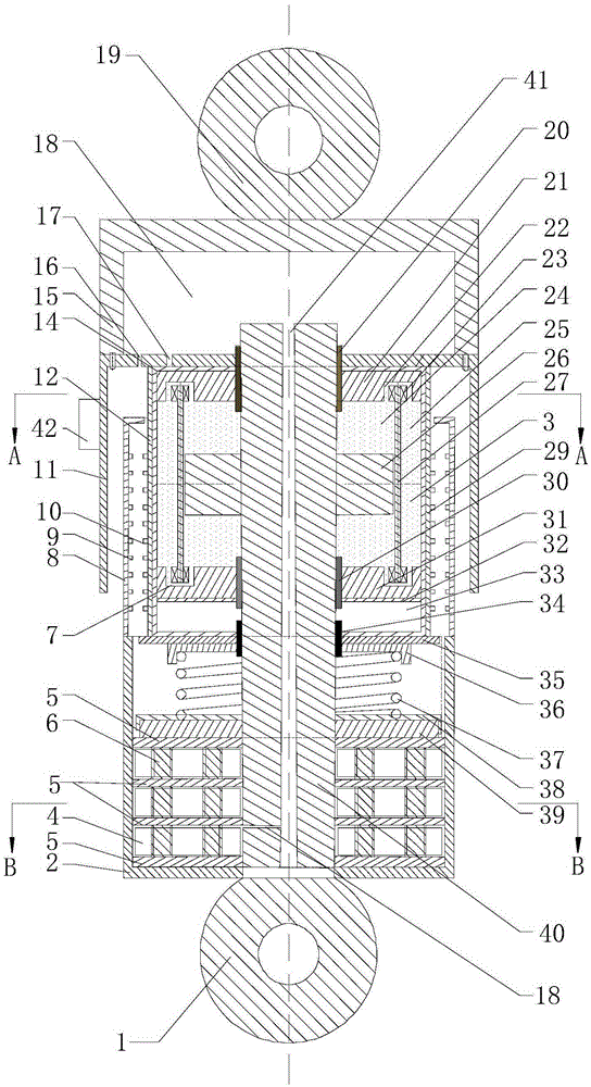
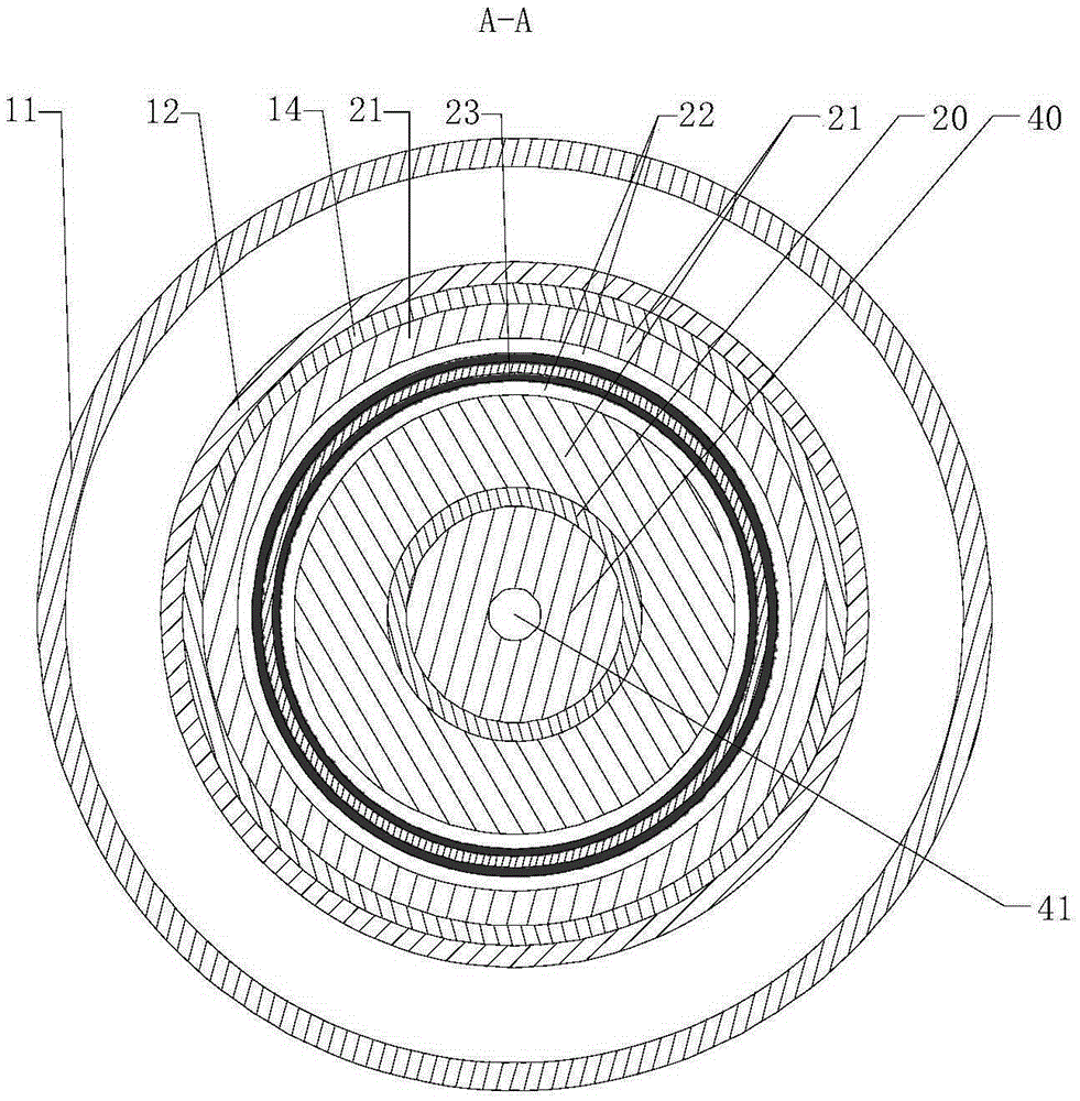
[0125] Such as figure 1 , figure 2 , image 3 and Figure 4 The shown self-powered vehicle vibration damping device includes a vibration damping device body and a vibration damping device controller 13. The vibration damping device body includes a first cylinder body 2 and passes through the first cylinder body 2 from bottom to top. The piston rod 40, and the piezoelectric generating unit, force transmission spring unit, magnetorheological damping unit and electromagnetic induction unit;

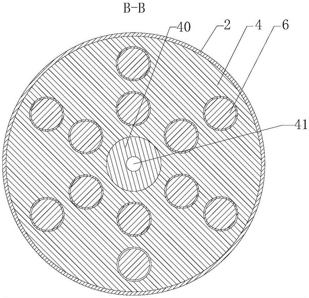
[0126] The piezoelectric generating unit includes a plurality of piezoelectric modules 4 arranged at the bottom of the first cylinder 2 and bonded alternately by double-sided adhesive thin iron plates 5, each of the piezoelectric modules 4 is embedded with a plurality of Piezoelectric vibrator 6; the piezoelectric module 4 at the bottom is bonded to the inner bottom wall of the first cylinder body 2 through a double-sided adhesive thin iron plate 5; during specific implementation, the do...


PUM

PropertyMeasurementUnit
Thicknessaaaaaaaaaa

Abstract

The invention discloses a self-powered vehicle vibration damping device which comprises a vibration damping device body and a vibration damping device controller, wherein the vibration damping device body comprises a first cylinder body, a piston rod, a piezoelectric generating unit, a transmission force spring unit, a magneto-rheological damping unit and an electromagnetic induction unit; the piezoelectric generating unit comprises a plurality of piezoelectric modules, and a plurality of piezoelectric vibrators are inlaid in each piezoelectric module; the transmission force spring unit comprises an upper spring pressing plate, a lower spring pressing plate, a lower spring clamping seat, an upper spring clamping seat and a transmission force spring; the magneto-rheological damping unit comprises an outer cylinder, an inner cylinder, a permanent magnet protecting cover, an upper damp channel, a lower damp channel, a magnet exciting coil and a piston; and the electromagnetic induction unit comprises a leakage-proof magnetic sleeve, a second cylinder body, a permanent magnet and an electromagnetic induction coil. The invention further discloses a control method for the self-powered vehicle vibration damping device. The self-powered vehicle vibration damping device provided by the invention is high in energy-regenerative efficiency, good in work stability, high in reliability, can adjust the damping force in real time, and ensures that a vehicle is in an optimal vibration damping state.

Description

technical field [0001] The invention belongs to the technical field of vehicle vibration damping devices, and in particular relates to a self-powered vehicle vibration damping device and a control method thereof. Background technique [0002] Magnetorheological fluid is an ideal intelligent material, which can change from a well-flowing liquid to a viscous fluid in a short time under the action of a magnetic field. It has certain yield characteristics, and its yield strength increases with the increase of the magnetic field intensity. The magnetorheological damper manufactured by using this characteristic of magnetorheological fluid has the advantages of wide range of damping characteristics and easy control under the action of an external magnetic field. With a certain control strategy, the magnetorheological damper can become An ideal semi-active control damper with excellent performance, compared with the existing damper, can achieve the purpose of controlling the damping...

Claims


Application Information

Patent Timeline
IPC IPC(8): F16F9/53
CPCF16F9/535
Inventor 寇发荣
Owner XIAN UNIV OF SCI & TECH
Why Eureka
Try Eureka