
Conversion device for high temperature modal test and vibration test method

A conversion device, vibration testing technology, applied in vibration testing, mechanical component testing, machine/structural component testing, etc., can solve the problem of inaccurate measurement results, large vibration signal errors, and inability to accurately obtain thermal modal vibration signal and other problems to achieve the effect of reducing errors and saving prices

Inactive Publication Date: 2019-10-22
CASIC DEFENSE TECH RES & TEST CENT
View PDF7 Cites 2 Cited by
  • Summary
  • Abstract
  • Description
  • Claims
  • Application Information

AI Technical Summary

Problems solved by technology

[0003] Since the vibration signal of the test piece structure needs to be collected in a thermal environment as high as 1000°C, the maximum measurement temperature of the high-temperature acceleration sensor cannot meet the requirements and cannot be used. The non-contact measurement method is easily affected by the quartz lamp tube during high-temperature heating. It leads to inaccurate measurement results. At the same time, if the gap between the quartz lamp tubes is too large, the consistency of the surface temperature of the test piece cannot be guaranteed. Therefore, it is necessary to design a test method for vibration signal acquisition in thermal modal tests to convert the high temperature test environment into Normal temperature environment for testing
[0004] In the existing test method, the temperature environment below 650°C is tested with a high-temperature acceleration sensor, and the laser is generally used for non-contact measurement above 650°C. The vibration signal has a large error, and the signal of thermal mode vibration cannot be accurately obtained

Method used

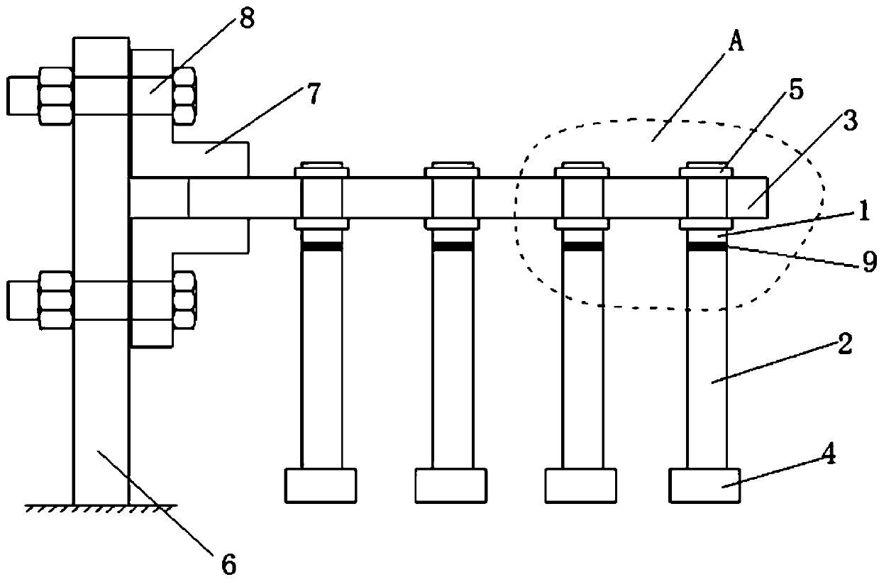
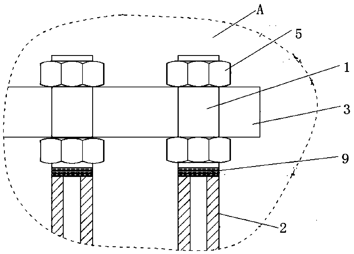
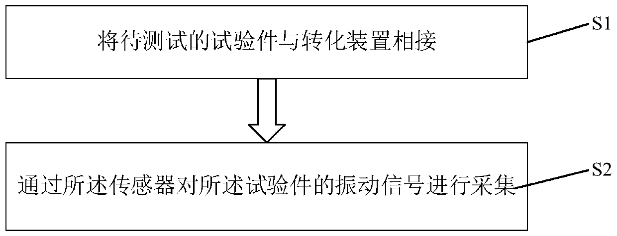

Image

  • Conversion device for high temperature modal test and vibration test method
  • Conversion device for high temperature modal test and vibration test method
  • Conversion device for high temperature modal test and vibration test method

Examples


Embodiment Construction

[0026] In order to make the object, technical solution and advantages of the present invention clearer, the present invention will be described in further detail below in conjunction with specific embodiments and with reference to the accompanying drawings.

[0027] Embodiments of the present invention are described in detail below, examples of which are shown in the drawings, wherein the same or similar reference numerals designate the same or similar elements or elements having the same or similar functions throughout. The embodiments described below by referring to the figures are exemplary only for explaining the present invention and should not be construed as limiting the present invention.

[0028] Those skilled in the art will understand that unless otherwise stated, the singular forms "a", "an", "said" and "the" used herein may also include plural forms. It should be further understood that when an element is referred to as being "connected" or "coupled" to another el...


PUM


Abstract

The invention discloses a conversion device for a high temperature modal test and a vibration test method. The conversion device comprises at least one conversion portion. The conversion portion comprises a metal rod, a connection rod and a sensor, wherein the metal rod is vertically arranged with an axial direction of a test piece which is about to carry out vibration testing and the test piece passes through the metal rod; the connection rod is connected with a lower end of the metal rod and an axis of the connection rod is arranged oppositely to the axis of the metal rod; and the sensor used for testing a vibration signal of the test piece is connected to the lower end of the connection rod.

Description

technical field [0001] The invention relates to the technical field of testing vibration signal collection in high-temperature modal tests, in particular to a conversion device and a vibration testing method for high-temperature modal tests. Background technique [0002] In the thermal modal test, since it is known that the maximum temperature that the high-temperature acceleration sensor can withstand is 650°C, it is urgent to invent a method that can accurately collect vibration signals under the action of a high temperature of 1000°C. [0003] Since the vibration signal of the test piece structure needs to be collected in a thermal environment as high as 1000°C, the maximum measurement temperature of the high-temperature acceleration sensor cannot meet the requirements and cannot be used. The non-contact measurement method is easily affected by the quartz lamp tube during high-temperature heating. It leads to inaccurate measurement results. At the same time, if the gap be...

Claims


Application Information

Patent Timeline
IPC IPC(8): G01M7/02G01M13/00
CPCG01M7/02G01M13/00
Inventor 王毅马璐军庞家志杨仕超李健
Owner CASIC DEFENSE TECH RES & TEST CENT
Learn More