
A laser control method and related equipment

A control method and laser technology, applied in the field of lasers, can solve problems such as computational resources, complexity, and long processing process that cannot guarantee control accuracy, and achieve the effects of simplifying processing and control processes, ensuring control accuracy, and improving processing efficiency

Active Publication Date: 2021-07-20
SU ZHOU MAXPHOTONICS CO LTD +1
View PDF7 Cites 0 Cited by
  • Summary
  • Abstract
  • Description
  • Claims
  • Application Information

AI Technical Summary

Problems solved by technology

[0004] In view of this, an embodiment of the present invention provides a laser control method, a laser, a laser control electronic device, and a storage medium to solve the problem that the existing control method has a long and complicated processing process and cannot avoid serious CPU consumption while ensuring control accuracy. Computing Resource Issues

Method used


Image

  • A laser control method and related equipment
  • A laser control method and related equipment
  • A laser control method and related equipment

Examples


Embodiment Construction

[0051] In order to enable those skilled in the art to better understand the solutions of the present invention, the technical solutions in the embodiments of the present invention will be clearly and completely described below in conjunction with the drawings in the embodiments of the present invention. Unless otherwise defined, all technical and scientific terms used herein have the same meaning as commonly understood by one of ordinary skill in the technical field of the invention.

[0052] The appearances of the phrase "an embodiment" in various places in the specification are not necessarily all referring to the same embodiment, nor are separate or alternative embodiments mutually exclusive of other embodiments. It is understood explicitly and implicitly by those skilled in the art that the embodiments described herein can be combined with other embodiments.

[0053] refer to figure 2 , the embodiment of the present invention discloses a laser control method for laser ou...


PUM


Abstract

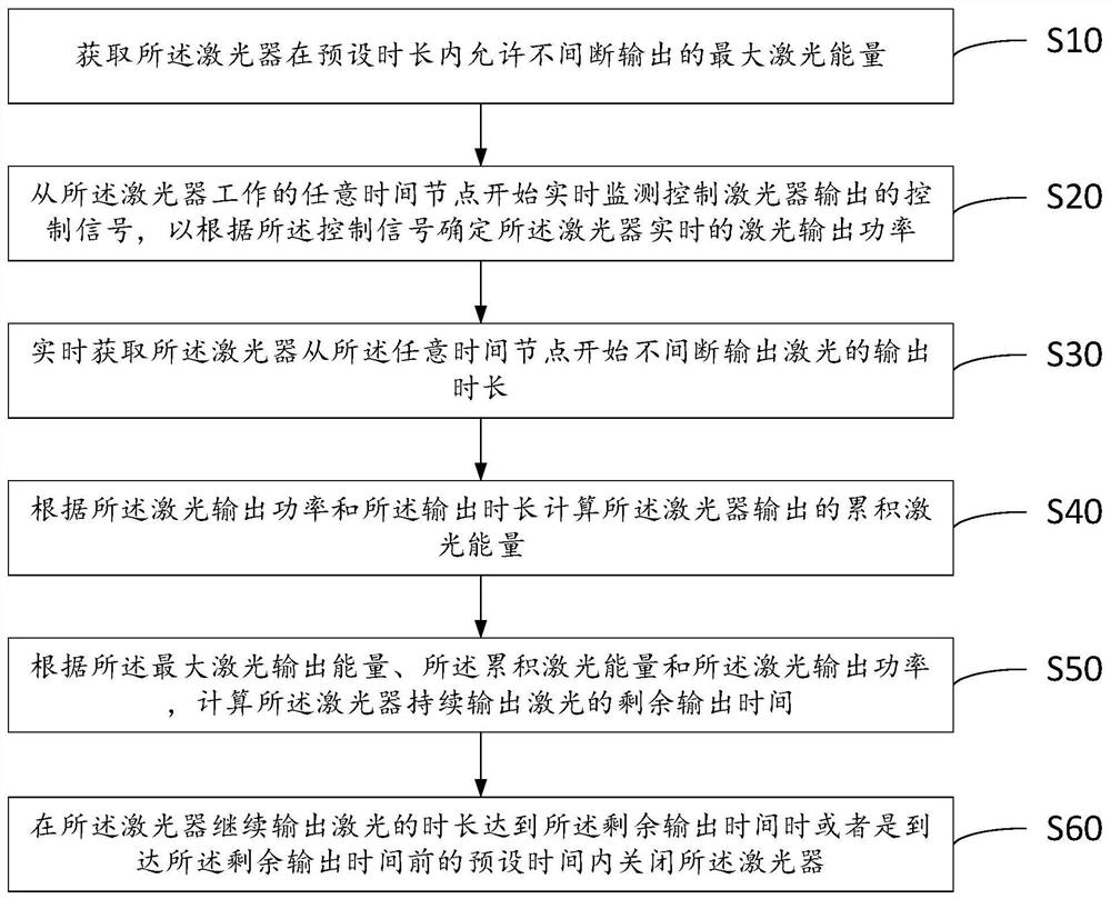
The invention discloses a laser control method and related equipment. The method includes: obtaining the maximum laser energy that the laser is allowed to output uninterruptedly within a preset time period; monitoring and controlling the control signal output by the laser in real time to determine the real-time The laser output power of the laser; real-time acquisition of the output duration of the laser output laser; calculate the cumulative laser energy output by the laser according to the laser output power and the output duration; according to the maximum laser output energy, the cumulative laser energy and the laser output power, calculate the remaining output time for the laser to continue to output laser light; when the laser continues to output laser light for the remaining output time or within a preset time before reaching the remaining output time, turn off the laser. The solution provided by the embodiment of the present invention controls the laser in a timing control manner, which can reduce the occupation of CPU computing resources while ensuring control accuracy.

Description

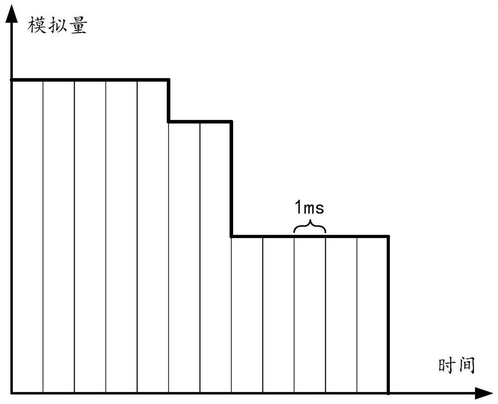
technical field [0001] Embodiments of the present invention belong to the technical field of lasers, and in particular relate to a laser control method, a laser, a laser control electronic device, and a storage medium. Background technique [0002] In the use of the laser, the analog signal output by the external laser control board is often used as the control signal to control the laser output power of the laser. [0003] In order to realize the self-protection of the laser, it is necessary to limit the size of the laser energy output by itself. For example, for a pulsed laser, the laser energy output by the pulsed laser within a certain period of time cannot exceed a certain set value N joules. The inventor is studying the present invention During the process, it was found that the practice in the prior art is to collect the analog signal output by the external laser control board through a certain sampling period, for example, to collect an analog signal once in 1 millis...

Claims


Application Information

Patent Timeline
Patent Type & Authority Patents(China)
IPC IPC(8): H01S3/10H01S5/06
CPCH01S3/10H01S5/06
Inventor 何高锋蒋峰
Owner SU ZHOU MAXPHOTONICS CO LTD
Learn More