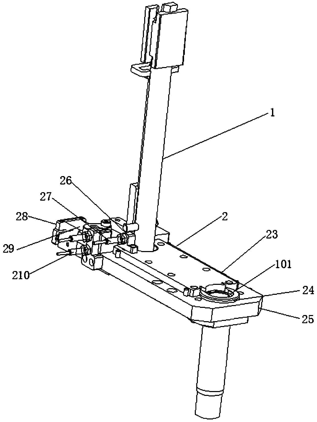
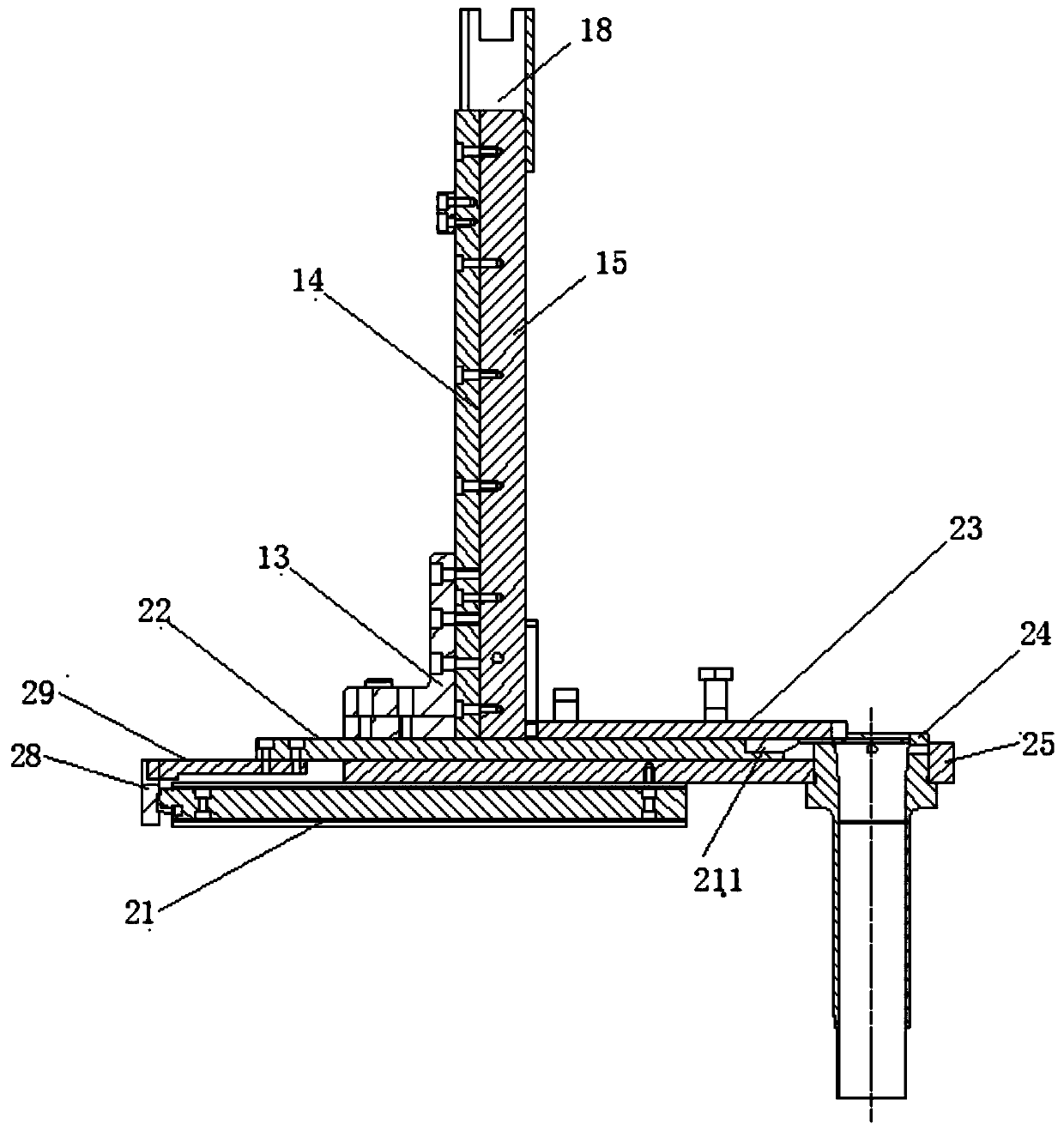
Automatic feeding and pressing equipment for elastic retainer ring for holes

An elastic retaining ring for holes and automatic feeding technology, applied in the direction of conveyor, conveyor objects, transportation and packaging, etc., can solve the problems of large consumption, affecting assembly efficiency, unable to press-fit the elastic retaining ring normally, and achieve smooth falling. Feeding, improve the effect of feeding efficiency

Pending Publication Date: 2019-10-25
ZHEJIANG ASIA PACIFIC MECHANICAL & ELECTRONICS
View PDF0 Cites 5 Cited by
  • Summary
  • Abstract
  • Description
  • Claims
  • Application Information

AI Technical Summary

Problems solved by technology

Due to the opening and the large amount of elastic retaining rings, they are easily nested together during the feeding process. When installing the retaining rings in the automatic assembly line, it is easy to affect the assembly efficiency
[0003] refer to Image 6 As shown, for the caliper 4, a retaining ring groove 411 is provided in the mounting hole 41, and a fixing frame 42 and a compression spring 43 are installed at the same time. Under the action of the compression spring 43, the fixing frame 42 will move upward and block the The radially inner space of the retaining ring groove 411 causes the elastic retaining ring to be unable to be pressed in normally, so the elastic retaining ring cannot be normally press-fitted with a conventional indenter

Method used


Image

  • Automatic feeding and pressing equipment for elastic retainer ring for holes
  • Automatic feeding and pressing equipment for elastic retainer ring for holes
  • Automatic feeding and pressing equipment for elastic retainer ring for holes

Examples


Embodiment Construction

[0029] The following will clearly and completely describe the technical solutions in the embodiments of the present invention with reference to the accompanying drawings in the embodiments of the present invention. Obviously, the described embodiments are only some, not all, embodiments of the present invention. The following description of at least one exemplary embodiment is merely illustrative in nature and in no way taken as limiting the invention, its application or uses. Based on the embodiments of the present invention, all other embodiments obtained by persons of ordinary skill in the art without creative efforts fall within the protection scope of the present invention.

[0030] Those skilled in the art can understand that, under the condition of no conflict, the features in the following embodiments and implementation manners can be combined with each other.

[0031] The terminology used herein is for the purpose of describing particular embodiments only and is not i...


PUM


Abstract

The invention discloses automatic feeding and pressing equipment for an elastic retainer ring for holes. The automatic feeding and pressing equipment comprises a material tower assembly, an air cylinder feeding assembly and a floating pressure head assembly, wherein the material tower assembly comprises a material tower which is vertically arranged and is connected with a positioning key strip onthe side surface, the elastic retainer ring is nested in the material tower in a sliding mode and is matched with the positioning key strip, the air cylinder feeding assembly comprises a base with a material channel, a guide sleeve connected with the tail end of the material channel and a material pushing plate for pushing the elastic retainer ring falling from the material tower to the guide sleeve along the material channel, the material pushing plate is driven by an air cylinder, the floating pressure head assembly comprises a pressing rod sleeve with an inner hole, a connecting rod is connected to the upper part of the pressing rod sleeve, a self-adjusting spring and a sliding sleeve are arranged in the pressing rod sleeve, a connecting screw is connected between the connecting rod andthe sliding sleeve, the self-adjusting spring sleeves the connecting screw and the upper end of the self-adjusting spring is connected with the connecting rod, and the lower end of the self-adjustingspring is connected with the sliding sleeve. According to the automatic feeding and pressing equipment, automatic interval feeding can be realized and correct press fitting of the elastic retainer rings for caliper holes can be realized.

Description

technical field [0001] The invention relates to an assembly technology of an elastic retaining ring for a hole, in particular to an automatic feeding and pressing equipment for an elastic retaining ring for a hole. Background technique [0002] Retaining rings are also called circlips, which are widely used in steering gears, calipers, etc. Since the retaining ring has an opening and is used in a large amount, it is easy to be nested together during the feeding process. When installing the retaining ring in the automatic assembly line, it is easy to affect the assembly efficiency. [0003] refer to Figure 6 As shown, for the caliper 4, a retaining ring groove 411 is provided in the mounting hole 41, and a fixing frame 42 and a compression spring 43 are installed at the same time. Under the action of the compression spring 43, the fixing frame 42 will move upward and block the The radial inner space of the retaining ring groove 411 causes the elastic retaining ring to be un...

Claims


Application Information

Patent Timeline
Patent Type & Authority Applications(China)
IPC IPC(8): B65G47/08B65G59/06B65G47/82
CPCB65G47/084B65G59/067B65G47/82B65G2201/0214
Inventor 吴继乐吴新中金杨杨
Owner ZHEJIANG ASIA PACIFIC MECHANICAL & ELECTRONICS
Why Eureka
Try Eureka