
Lamplight tracking system and excavator

A technology for tracking systems and excavators, applied to earth movers/excavators, construction, etc., to achieve the effects of improving excavation efficiency, improving vision, and improving construction safety

Inactive Publication Date: 2019-10-25
SANY HEAVY MACHINERY
View PDF6 Cites 2 Cited by
  • Summary
  • Abstract
  • Description
  • Claims
  • Application Information

AI Technical Summary

Problems solved by technology

When the excavator is working, the vision and lighting around the bucket are very important. However, at present, the night lighting of the excavator is mostly fixed, and there are certain limitations in the lighting during specific construction.

Method used


Image

  • Lamplight tracking system and excavator
  • Lamplight tracking system and excavator
  • Lamplight tracking system and excavator

Examples


Embodiment 1

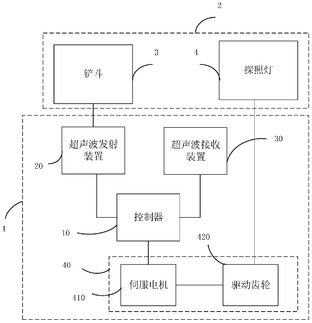
[0049] Please refer to figure 1, this embodiment proposes a light tracking system 1, which can be applied to the excavator 2. By positioning the bucket 3 of the excavator 2, the searchlight 4 is controlled to automatically track the bucket 3, which can improve the safety of night work sex etc. The light tracking system 1 will be described in detail below.

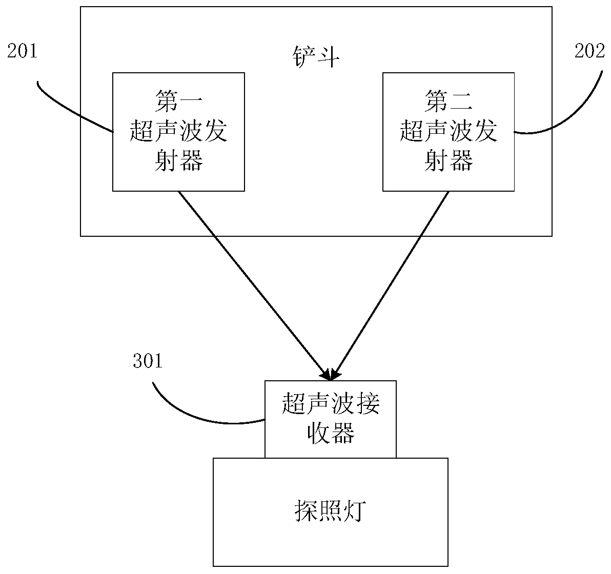
[0050] Such as figure 1 As shown, the light tracking system 1 includes: a controller 10 and an ultrasonic transmitting device 20 connected to the controller 10, an ultrasonic receiving device 30, and a driving device 40, wherein the driving device 40 is connected to the searchlight 4 of the excavator 2 , the ultrasonic emitting device 20 is arranged on the bucket 3 of the excavator 2 .

[0051] The controller 10 can be used to send an activation signal to notify the ultrasonic emitting device 20 to transmit ultrasonic signals when the light tracking system 1 needs to be activated.

[0052] Optionally, the light tracking...

Embodiment 2

[0080] Please refer to figure 1 , based on the above-mentioned embodiment 1, this embodiment proposes an excavator 2, the excavator 2 includes a bucket 3, a searchlight 4 and a light tracking system 1, wherein the light tracking system 1 can use the light in the above-mentioned embodiment 1 tracking system.

[0081] Exemplarily, the light tracking system 1 includes a controller 10 and an ultrasonic transmitting device 20, an ultrasonic receiving device 30, and a driving device 40 respectively connected to the controller 10, and the driving device 40 is connected to the searchlight 4, so The ultrasonic emitting device 20 is arranged on the bucket 3;

[0082] The controller 10 is configured to send an activation signal to the ultrasonic emitting device 20;

[0083] The ultrasonic emitting device 20 is used for emitting an ultrasonic signal after receiving the activation signal;

[0084] The controller 10 is also used to calculate the position information of the bucket accordi...


PUM


Abstract

The invention provides a lamplight tracking system and an excavator. The system comprises a controller, an ultrasonic transmitting device, an ultrasonic receiving device and a drive device, wherein the ultrasonic transmitting device, the ultrasonic receiving device and the drive device are connected with the controller. The drive device is connected with a searchlight of the excavator. The ultrasonic transmitting device is arranged on a bucket of the excavator. The controller is used for sending a startup signal to the ultrasonic transmitting device. The ultrasonic transmitting device is usedfor transmitting an ultrasonic signal after receiving the startup signal. The controller is further used for calculating the location information of the bucket according to the ultrasonic signal received by the ultrasonic receiving device, confirming the rotating angle according to the location information and the current angle of the searchlight and driving the drive device according to the rotating angle so as to turn the searchlight to the bucket. According to the technical scheme, automatic tracking of the searchlight to the bucket of the excavator can be achieved, the view of a driver isimproved to a great degree, and excavation efficiency, construction safety and the like can be improved.

Description

technical field [0001] The invention relates to the technical field of engineering machinery, in particular to a light tracking system and an excavator. Background technique [0002] In modern construction, excavators, as the main equipment for earthwork excavation, occupy an important position in modern construction machinery, and are widely used in mining, industrial and civil construction, agricultural machinery engineering, transportation, port construction and military engineering Construction and other projects. Due to the complex and changeable construction environment, excavators often work at night or in dimly lit conditions such as mines and tunnels. Therefore, it is very important to improve the efficiency and safety of excavators in such working conditions. When the excavator is working, the vision and lighting around the bucket are very important. However, at present, the night lighting of the excavator is mostly fixed, and there are certain limitations in the ...

Claims


Application Information

Patent Timeline
Patent Type & Authority Applications(China)
IPC IPC(8): E02F9/20E02F9/26
CPCE02F9/20E02F9/264E02F9/265
Inventor 付志伟宁静陈华
Owner SANY HEAVY MACHINERY
Learn More