
Antenna reflector and its surface deformation measurement method and comparative measurement method

A technology of antenna reflector and measurement method, which is applied in the direction of measuring devices, instruments, etc., can solve the problems of cumbersome operation, large deviation, time-consuming and laborious, etc.

Active Publication Date: 2020-07-21
DALIAN UNIV OF TECH
View PDF10 Cites 0 Cited by
  • Summary
  • Abstract
  • Description
  • Claims
  • Application Information

AI Technical Summary

Problems solved by technology

[0004] In order to solve the problem that there is a large deviation in the current measurement of the antenna reflector surface deformation, or the operation is cumbersome and time-consuming, the present invention proposes a method for measuring the antenna reflector surface deformation. The method has simple steps during measurement and can save Time-saving and labor-saving, with high measurement accuracy, and further solved the problem of dynamic deformation measurement of the reflector surface

Method used


Image

  • Antenna reflector and its surface deformation measurement method and comparative measurement method
  • Antenna reflector and its surface deformation measurement method and comparative measurement method
  • Antenna reflector and its surface deformation measurement method and comparative measurement method

Examples


Embodiment 1

[0061] Embodiment 1: This embodiment records a method for measuring surface deformation based on a grid reflector, which can improve the overall deformation measurement accuracy for spatial continuity features, including the following steps:

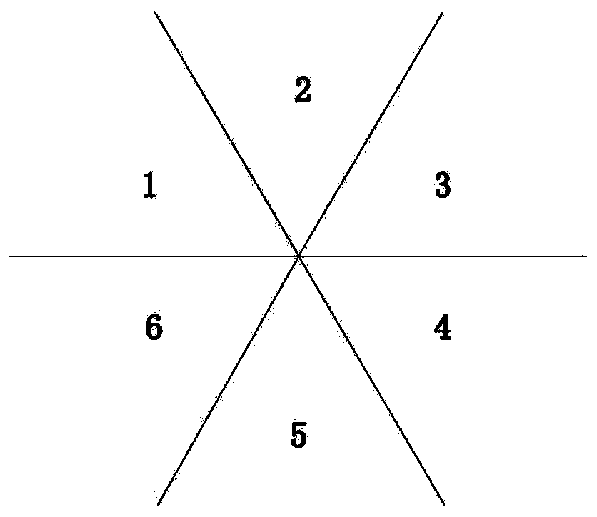
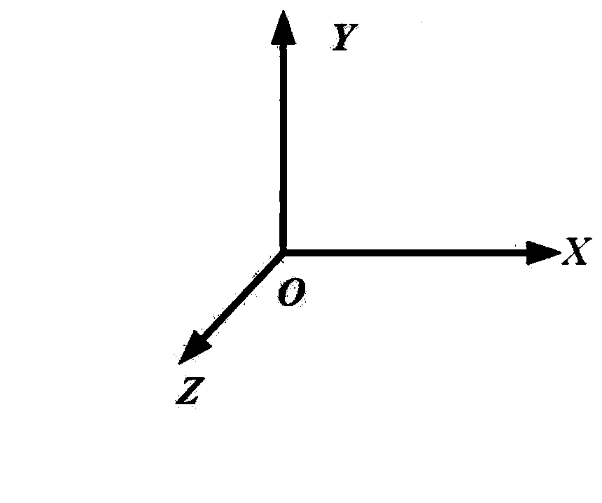
[0062] S1: Arrange multiple targets on the surface of the reflector, increase the density of the targets per unit area as much as possible, use the sensor to measure the three-dimensional coordinates of the targets, the origin of the coordinate system is placed in the center of the structure, and the Z axis is parallel to the surface The deformation direction, the large deformation direction is unique, the XY plane is perpendicular to the Z axis, and the small deformation occurring in the XY plane has little influence on the performance of the grid reflector, so this embodiment does not consider it.

[0063] S2: According to the surface characteristics of the structure and the requirement for the number of target points by polynomial fitt...

Embodiment 2

[0073] Embodiment 2: In this embodiment, the method of taking a single measurement of the sensor and taking the average value of multiple measurements is used as a comparative example, and is compared with the measurement method of the present invention. Through the experimental results, it is shown that the method of the present invention can effectively reduce the The deviation of the single measurement of the sensor improves the overall deformation measurement accuracy of the reflector surface, that is, the spatial continuity feature is used to improve the overall deformation measurement accuracy, and the operation is simple, saving time and effort.

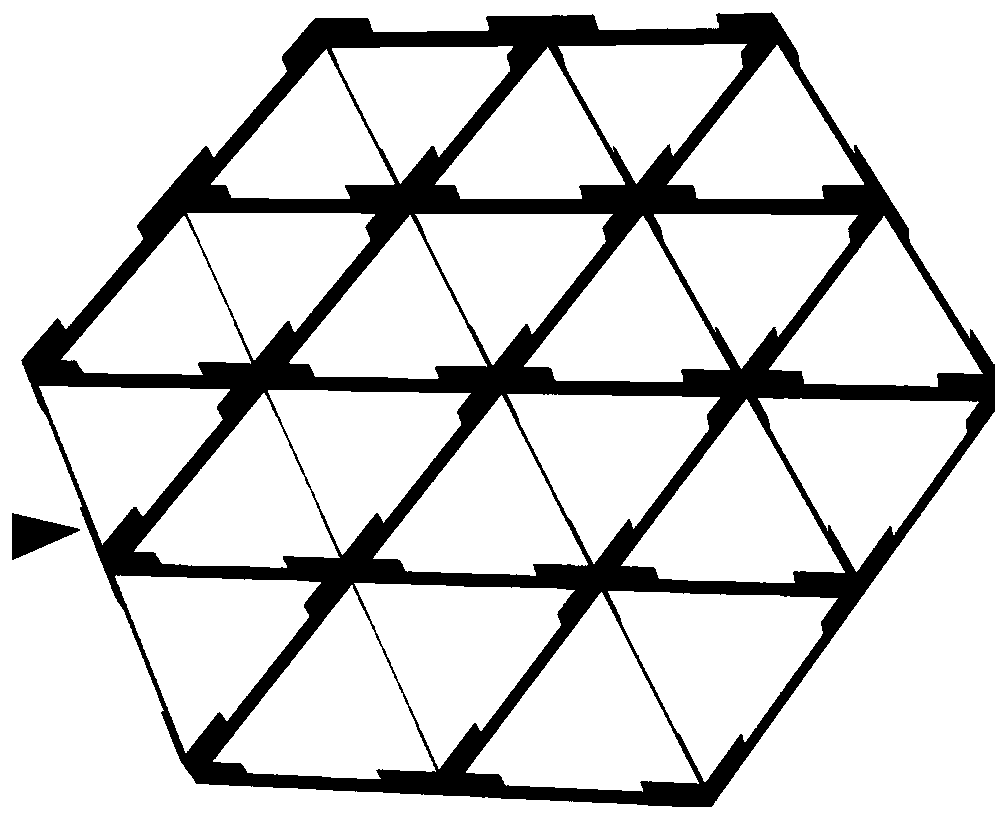
[0074] Taking the regular hexagonal grid reflector as an example, its projection diameter is 0.6 meters, and 30 PZT piezoelectric actuators are installed in the U-shaped groove on the back of the reflector. There are 178 PZT piezoelectric actuators with a diameter of 1.6 centimeter target. DIC (three-dimensional optical speckl...


PUM


Abstract

The invention provides an antenna reflector, a profile deformation measuring method thereof and a comparative measuring method thereof, belonging to the field of overall deformation measurement. In order to solve the problem that the current deformation measurement for a grid reflector profile has a large deviation or cumbersome operation and time and labor consumption problem, the main point is that a plurality of target points are arranged on a reflector profile, the three-dimensional coordinates of the target points are measured, and a single measurement is performed on the deformation displacement of the target points of the reflector profile by a sensor. The reflector profile is divided into multiple fitting areas. The coordinate information of the target points in different fitting regions is fitted and the deformation displacement of the corresponding target points is set, and a polynomial coefficient is solved by the least squares method to obtain a fitting function corresponding to each piece of the fitting regions. The coordinate information of the target points in different areas is substituted into the fitting function of the corresponding region, and the deformation displacement of the corresponding target is updated and obtained. The invention has the advantages that the overall deformation measurement accuracy is improved by using a spatial continuity feature, the operation is simple, and time and labor are saved.

Description

technical field [0001] The invention belongs to the field of overall deformation measurement and relates to a method for measuring the surface deformation of an antenna reflector. Background technique [0002] High-precision solid-surface antenna reflectors, such as grid reflectors, are widely used in satellite communications, earth observation, and deep space exploration. It needs to maintain a high surface accuracy in the working state to meet the requirements of its working frequency. However, it is affected by factors such as space thermal load, structural relaxation and material creep, which will lead to deformation of the reflector surface, making its shape The accuracy of the surface decreases, and it is necessary to measure the deformation of the surface and adjust it. [0003] At present, it is often used to determine the surface deformation of the reflector by using photogrammetry and other sensors to measure the average value of a single measurement or multiple m...

Claims


Application Information

Patent Timeline
Patent Type & Authority Patents(China)
IPC IPC(8): G01B21/32
CPCG01B21/32
Inventor 谭述君聂天智宋祥帅
Owner DALIAN UNIV OF TECH
Learn More