
Electrical left-right hand rule demonstrator

A right-handed, rule-based technology, applied in the field of teaching aids, can solve the problem that the demonstration device cannot satisfy students to consolidate knowledge

Active Publication Date: 2019-10-25
刘卫进
View PDF9 Cites 2 Cited by
  • Summary
  • Abstract
  • Description
  • Claims
  • Application Information

AI Technical Summary

Problems solved by technology

[0003] The purpose of the present invention is to overcome the defect that the existing demonstration device cannot satisfy students to consolidate knowledge through repeated operations, and to invent an electrical right-handed rule that can intuitively reflect the direction of the force on the conductor or the direction of the induced current in the magnetic field at any time demonstrator

Method used


Image

  • Electrical left-right hand rule demonstrator
  • Electrical left-right hand rule demonstrator
  • Electrical left-right hand rule demonstrator

Examples


Embodiment Construction

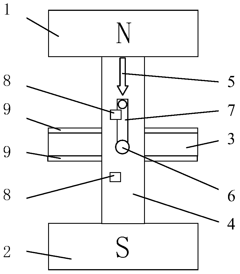
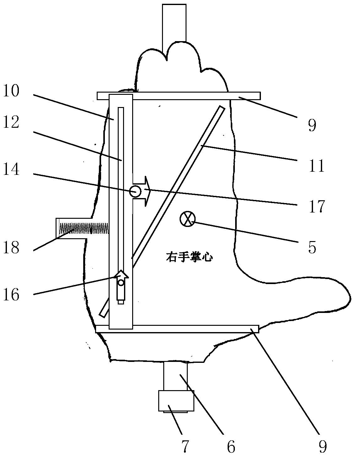
[0017] Such as figure 1 As shown, the demonstrator of the left and right hand rule of electricity includes a magnetic north pole 1, a magnetic south pole 2 and a palm 3, and the magnetic north pole 1 and the magnetic south pole 2 are connected in one body through a bracket 4 ( figure 1 Only the front support can be seen in the middle), the support 4 is marked with the magnetic field line 5, the palm 3 is arranged between the front and rear two supports 4 through the rotating shaft 6, one side of the palm 3 is the palm of the left hand, and the other side is the palm of the right hand, and the rotating shaft 6 is set Rocking arm 7 is arranged, and bracket 4 is respectively provided with a buckle 8 above and below rotating shaft 6, and buckle 8 is used for clamping rocking arm 7, and when rocking arm 7 is blocked, palm 3 will be in horizontal state; figure 2 image 3 As shown, the front and rear ends of palm 3 are provided with chute 9, and conductor 10 is arranged between two...


PUM


Abstract

The invention relates to a teaching aid, in particular to an electrical left-right hand rule demonstrator. The electrical left-right hand rule demonstrator comprises a magnetic north pole, a magneticsouth pole and a palm. The magnetic north pole and the magnetic south pole are connected into a whole through supports. The palm is arranged between a front support and a rear support through a rotating shaft. One side of the palm is a left palm, and the other side of the palm is a right palm. Sliding grooves are formed in the front end and the rear end of the palm. A conductor is arranged betweenthe two sliding grooves. An oblique groove is formed in the left palm center. A long hole is formed in the conductor. An external current arrow is inserted into the joint of the oblique groove and the long hole. A stress arrow is arranged on the left side of the conductor. The external current arrow is pushed upwards, and the conductor moves in the direction pointed by the stress arrow. The oblique groove is also formed in the center of the right palm, while the long hole is also formed in the conductor. The induced current arrow is inserted into the joint of the oblique groove and the long hole. A moving arrow is arranged on the right side of the conductor. When the conductor is pushed rightwards, the induced current arrow moves in the direction pointed by the arrow. The electrical left-right hand rule demonstrator can be used for demonstration at any time. The learned knowledge is consolidated through repeated operation.

Description

technical field [0001] The invention is a teaching aid, in particular a demonstrator of the left and right hand rule of electricity. Background technique [0002] The left-hand rule in electricity reflects the law of the force direction of the current-carrying conductor in the magnetic field, and the right-hand rule reflects the law of the direction of the induced current in the conductor when the conductor cuts the magnetic force line in the magnetic field. The demonstration of these two rules is generally realized through specific circuits, which requires preparing magnets, power supplies, wires and brackets for installing experimental equipment in the laboratory, and then assembling the circuits to complete the demonstration. Students demonstrate by themselves, which is good for improving the theoretical understanding, but there are also shortcomings. The main reason is that the demonstration requires a venue, equipment, assembly, and time. To meet these conditions, it is...

Claims


Application Information

Patent Timeline
Patent Type & Authority Applications(China)
IPC IPC(8): G09B23/18
CPCG09B23/181
Inventor 王美霞
Owner 刘卫进
Learn More