
Return card agency

A technology of card ejection mechanism and card tray, which is applied in the structure of telephone sets, coupling devices, branch office equipment, etc., can solve the problems of troublesome storage for users, difficulty in waterproof design, etc., and achieve the effect of convenient waterproof design

Active Publication Date: 2021-01-15
JUST CONNECTOR KUSN
View PDF8 Cites 0 Cited by
  • Summary
  • Abstract
  • Description
  • Claims
  • Application Information

AI Technical Summary

Problems solved by technology

The design of this solution has the following disadvantages. To return the card, an additional card return needle is required, which is troublesome for the user to keep; the card return needle needs to set a pin hole on the side of the mobile phone to push the push rod, and the pin hole must pass through to the mobile phone. The inner space pushes the push rod, and the waterproof design is more difficult

Method used


Image

  • Return card agency
  • Return card agency
  • Return card agency

Examples


Embodiment Construction

[0022] In order to make the purpose, technical solution and advantages of the present application clearer, the technical solution of the present application will be clearly and completely described below in conjunction with specific embodiments of the present application and corresponding drawings.

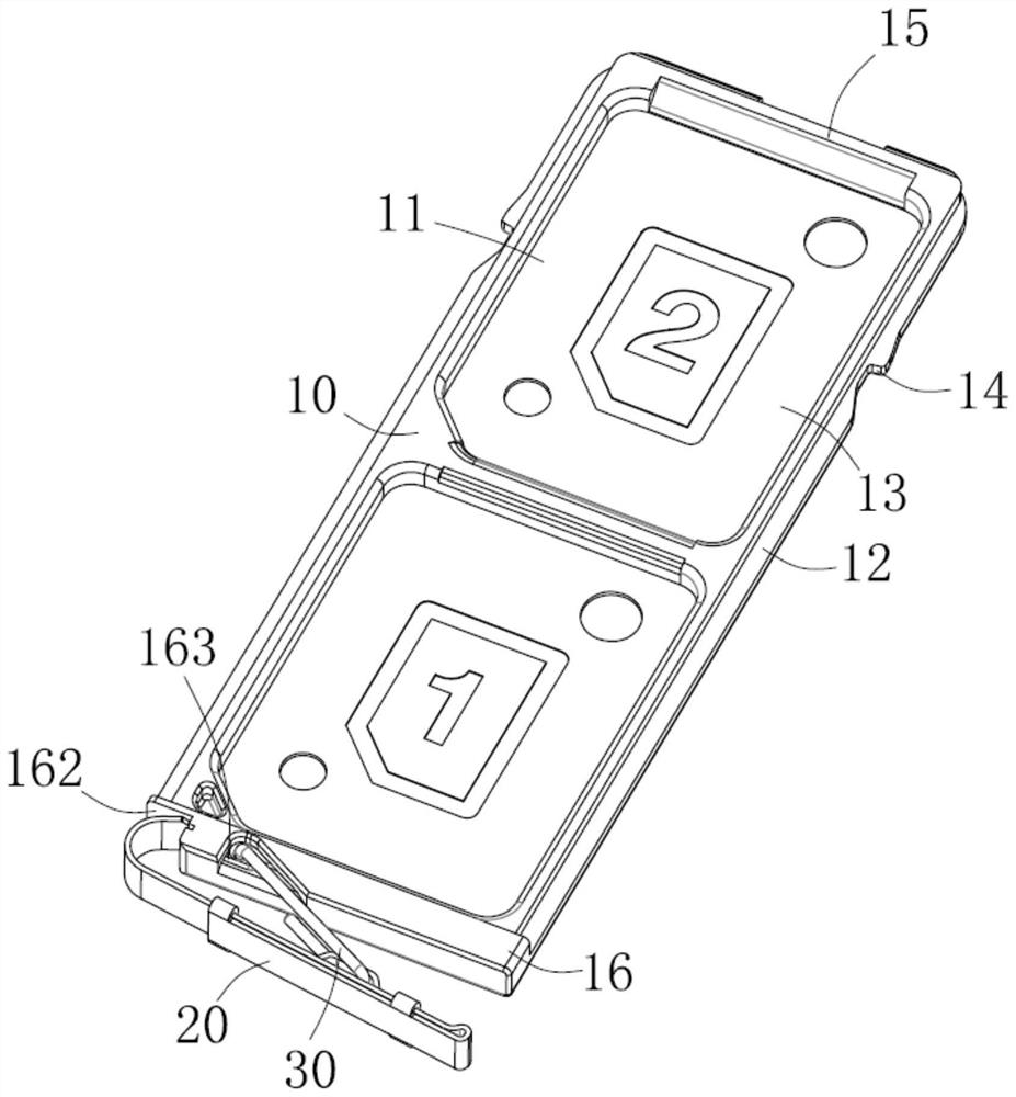
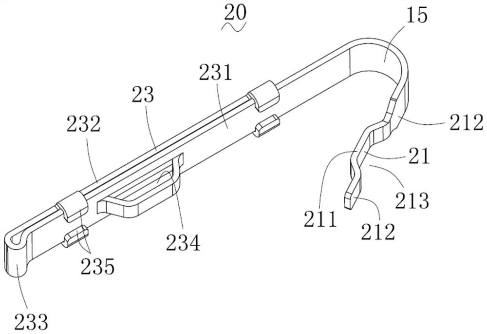
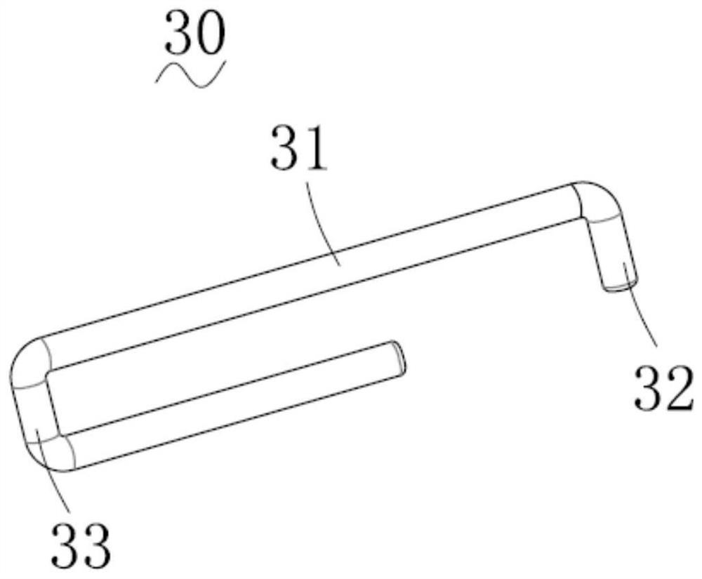
[0023] see Figure 1 to Figure 4 As shown, the card ejecting mechanism of the present application includes a card holder 10, an elastic member 20 fixed on the front end of the card holder 10, a connecting rod 30 and a cover plate 40 connecting the elastic member 20 and the front end of the card holder 20 (such as Figure 5 shown).

[0024] The card tray 10 includes a metal frame 11 and an insulator 12 formed outside the metal frame 11 . The metal frame 11 includes a base 111 and a wall 112 bent and extended from the base 111 . The insulator 12 is formed on the wall portion 112 and defines a card receiving space 13 with the base 111 . The insulator 12 includes an insertion end 1...


PUM


Abstract

The invention relates to a card withdrawing mechanism. The card withdrawing mechanism comprises a card holder, an elastic piece fixed at the front end of the card holder, a connecting rod connected the elastic piece with the front end portion of the card holder, and a cover plate, wherein the elastic piece comprises a fixed end fixed at the rear end portion of the card holder, a tensioning part formed by reverse bending from the fixed end, and a stressed arm formed by extending the tensioning part; the cover plate is tightly locked to achieve card insertion when the stressed arm is tightly pressed; and when the cover plate is released from locking, the stressed arm is popped out, and the stressed arm is pushed to pull out the card holder to achieve card withdrawing. The card withdrawing mechanism can perform card withdrawing with no need for a card withdrawing needle.

Description

technical field [0001] The application relates to the field of electrical connectors, especially to a card ejection mechanism. Background technique [0002] Most of the existing card holders use a push rod type card ejection mechanism, which requires the user to use a card ejection needle to insert into the card ejection hole to drive the push rod, and then use the cam mechanism to pry the tail of the card holder to push out the card holder to realize the ejection. Card. The design of this solution has the following disadvantages. To return the card, an additional card return needle is required, which is troublesome for the user to keep; the card return needle needs to set a pin hole on the side of the mobile phone to push the push rod, and the pin hole must pass through to the mobile phone. The inner space pushes the push rod, and the waterproof design is relatively difficult. Contents of the invention [0003] In view of this, it is necessary to provide a card return m...

Claims


Application Information

Patent Timeline
Patent Type & Authority Patents(China)
IPC IPC(8): H01R12/71H01R13/52H01R13/633H04B1/3818H04M1/02
CPCH01R12/714H01R13/52H01R13/633H01R2201/16H04M1/0274H04B1/3818
Inventor 杨伟
Owner JUST CONNECTOR KUSN
Learn More