Welding wire feeding device

A technology of feeding device and welding wire, applied in welding equipment, welding accessories, arc welding equipment, etc., can solve problems such as troublesome handling, and achieve the effect of improving workability and reducing frictional resistance.

Active Publication Date: 2019-10-29
DAIHEN CORP
View PDF10 Cites 0 Cited by
  • Summary
  • Abstract
  • Description
  • Claims
  • Application Information

AI Technical Summary

Problems solved by technology

Although the above-mentioned pulling side feeding device and the like are members that can be placed on the ground of the workplace, it is very troublesome fo

Method used


Image

  • Welding wire feeding device
  • Welding wire feeding device
  • Welding wire feeding device

Examples


Embodiment Construction

[0095] Hereinafter, preferred embodiments of the present invention will be specifically described with reference to the drawings.

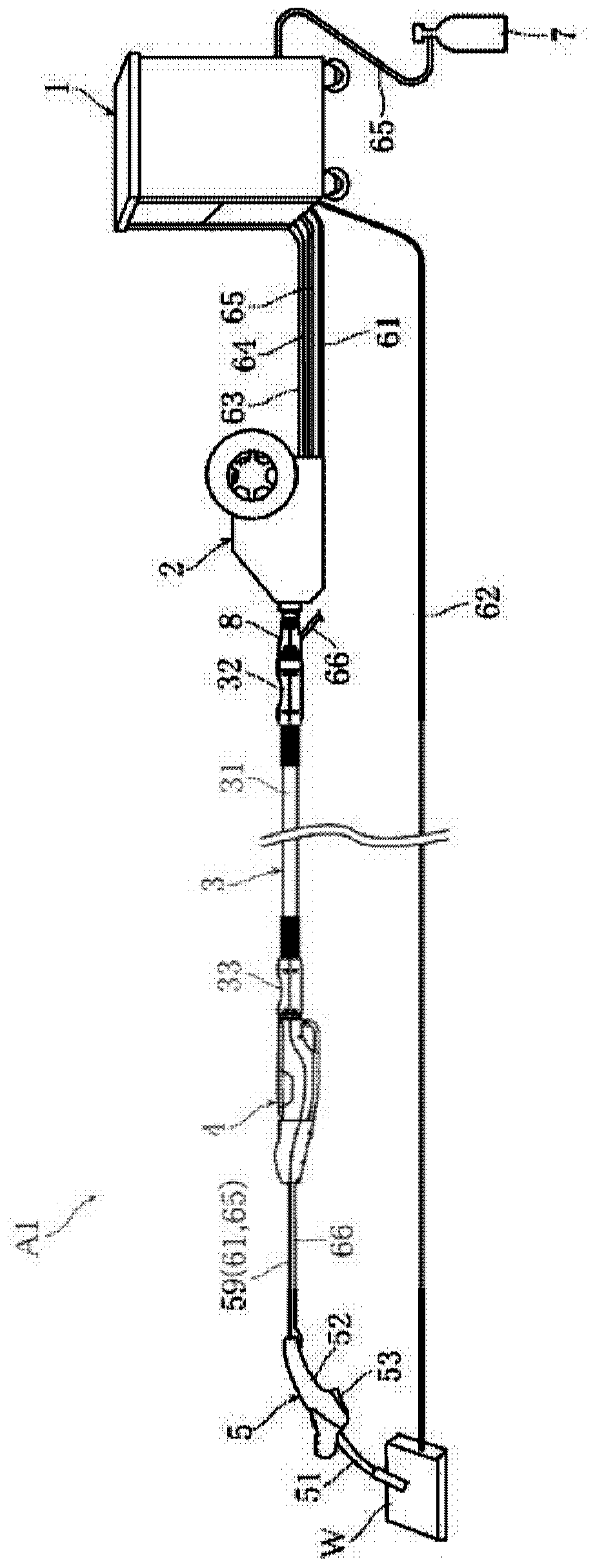
[0096] figure 1 , figure 2 It is an overall configuration diagram showing an example of a welding system including the wire feeding device of the present invention. Such as figure 1 As shown, the welding system A1 has a welding power supply device 1, a welding wire feeding device 2, an intermediate cable 3, a welding wire feeding device 4, a welding torch 5, a welding torch cable 59, cables 61, 62, a power transmission line 63, a signal Line 64, gas cylinder 7 and gas piping 65.

[0097] One output terminal of welding power supply device 1 is connected to welding torch 5 via cable 61 . The welding wire feeding devices 2 and 4 feed the welding wire to the welding torch 5 and make the tip of the welding wire protrude from the tip of the welding torch 5 . The cable 61 is electrically connected to the welding wire in the contact piece arranged a...


PUM


Abstract

The invention provides a welding wire feeding device suitable for improving the workability of a welding operation in semi-automatic welding. The welding wire feeding device (4) is provided with a casing (40) for accommodating a welding wire feeding mechanism and sends the welding wire in a predetermined feeding direction. The casing (40) has a cylindrical peripheral wall (41). The cylindrical peripheral wall includes a bottom wall (411) extending along the feeding direction, and first and second side walls standing up from one end and the other end in the width direction (Y) of the bottom wall. The cylindrical peripheral wall is provided with: a projection for the bottom wall, which protrudes in the direction of the bottom wall toward one end and the other end in the width direction of the bottom wall in front and rear of the feeding direction; a protrusion for the first side wall, which protrudes in the direction toward the first side wall at the lower end and the upper end of the first side wall, and forward and backward in the feeding direction; and a protrusion for the second side walls, which protrudes in the direction toward the second side wall at the lower end and the upper end of the second side wall and forwards and backwards in the feeding direction.

Description

technical field [0001] The invention relates to a welding wire feeding device. Background technique [0002] In consumable electrode gas shielded arc welding, automatic welding using a welding robot or a moving trolley, and semi-automatic welding by an operator are used. During welding work such as the above-mentioned automatic welding, the welding wire is fed to the welding torch by the welding wire feeder, and electric power and shielding gas are supplied to the welding torch. [0003] For example, in semi-automatic welding, a wire feeder and a welding torch are connected by a torch cable (for example, refer to Patent Document 1). In welding work, an operator operates a welding torch to weld a desired workpiece. Depending on the site where the welding work is performed, the work area may be relatively large. In such a case, an intermediate cable and an additional wire feeding device (pull-side feeding device) are provided between the above-mentioned wire feeding device ...

Claims


Application Information

Patent Timeline
IPC IPC(8): B23K9/133B23K9/32
CPCB23K9/133B23K9/32
Inventor 中村洋介清水文夫
Owner DAIHEN CORP
Why Eureka
Try Eureka