Liner hanging mechanism and door foaming die with same

A technology of ribs and installation cavity, which is applied in the field of door foaming molds, can solve the problems of material waste and affect production efficiency, and achieve the effect of ensuring production efficiency and avoiding material waste

Inactive Publication Date: 2019-10-29
合肥市奥兰德机械科技有限公司
View PDF0 Cites 0 Cited by
  • Summary
  • Abstract
  • Description
  • Claims
  • Application Information

AI Technical Summary

Problems solved by technology

[0003] The present invention proposes a lining mechanism and a door foaming mold with the lining mecha

Method used


Image

  • Liner hanging mechanism and door foaming die with same
  • Liner hanging mechanism and door foaming die with same
  • Liner hanging mechanism and door foaming die with same

Examples


Embodiment Construction

[0019] The following will clearly and completely describe the technical solutions in the embodiments of the present invention with reference to the accompanying drawings in the embodiments of the present invention. Obviously, the described embodiments are only some, not all, embodiments of the present invention. Based on the embodiments of the present invention, all other embodiments obtained by persons of ordinary skill in the art without making creative efforts belong to the protection scope of the present invention.

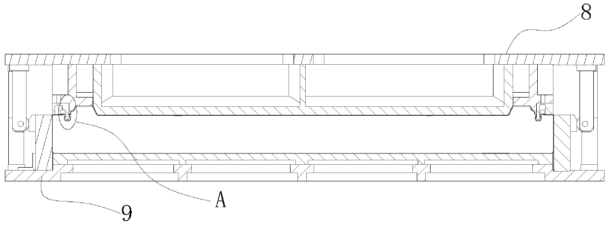
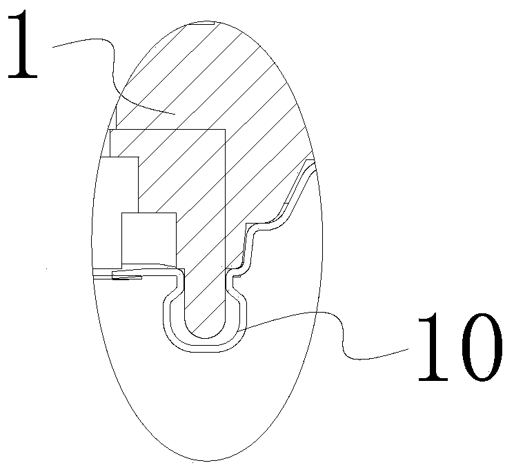
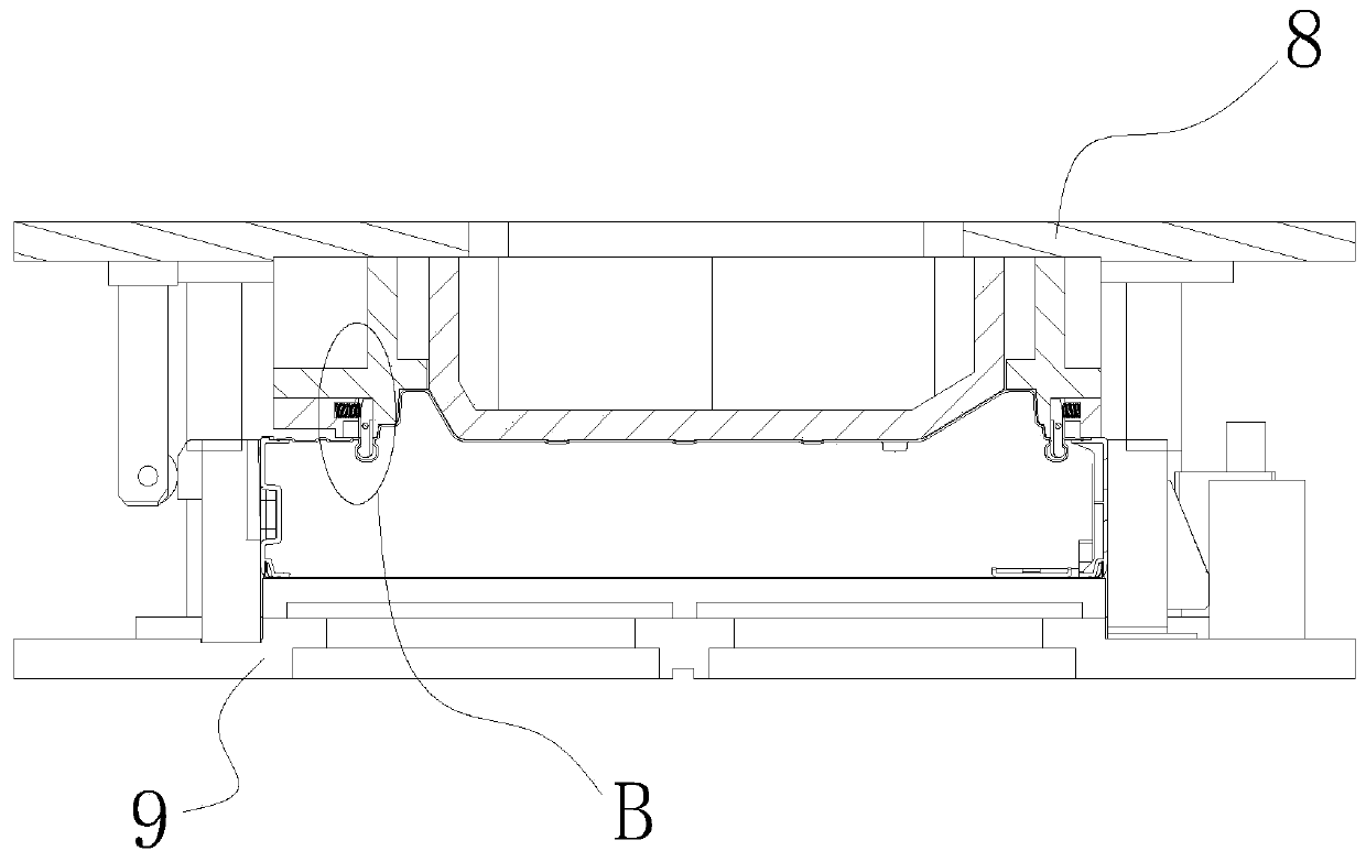
[0020] Such as Figure 1-5 as shown, figure 1 It is a longitudinal sectional view of a door foaming mold of the prior art; figure 2 for figure 1 Partial enlarged view of part A in middle; image 3 It is a longitudinal sectional view of a door foaming mold proposed by the present invention; Figure 4 for image 3 Partial enlarged view of part B in middle; Figure 5 It is a structural schematic diagram of a door foaming mold proposed by the present invent...


PUM


Abstract

The invention discloses a liner hanging mechanism and a door foaming die with the same. The liner hanging mechanism comprises a rib surrounding seat, liner hanging ribs and elastic tight-push parts; an installation cavity is disposed in the rib surrounding seat; the tops of the liner hanging ribs are located in the installation cavity; the bottoms of the liner hanging ribs extend out of the installation cavity; the liner hanging ribs are rotationally connected with the side wall of the installation cavity; the elastic tight-push parts tightly push one side walls of the upper sides of the linerhanging ribs, and the other side walls of the upper sides of the liner hanging ribs abut against the side wall of the installation cavity; liner hanging portions are disposed on the side walls of thelower sides of the liner hanging ribs; the liner hanging portions and the elastic tight-push parts are located on the same sides of the liner hanging ribs; and receding portions are disposed on the side walls of the sides, back on to the liner hanging portions, of the liner hanging ribs. The invention further provides the door foaming die with the liner hanging mechanism. Thus compared with the prior art, the liner hanging mechanism and the door foaming die with the same have the advantage that liner dropping is not prone to occurring during foaming, material waste is avoided, and then the production efficiency is guaranteed.

Description


Claims


Application Information

Patent Timeline
Owner 合肥市奥兰德机械科技有限公司
Why Eureka
Try Eureka