
Pressurizing device

A pressurizing device and a technology for installing holes, which are applied in textiles, papermaking, fabric surface trimming, etc., can solve problems such as increasing pressure, and achieve the effects of increasing pressure, simple structure, and convenient manufacture

Pending Publication Date: 2019-10-29
浙江泰坦股份有限公司
View PDF0 Cites 0 Cited by
  • Summary
  • Abstract
  • Description
  • Claims
  • Application Information

AI Technical Summary

Problems solved by technology

[0002] In textile machinery, in order to generate greater draft force for the fabric passing between two shafts, the general method is to increase the diameter of the shaft and use its own gravity to increase the pressure between the two shafts, thereby increasing the pressure on the fabric. Improve the drafting force of the fabric; some use springs at both ends of a shaft to increase the pressure between the two shafts by spring force, but this method can only increase the pressure at both ends of the shaft, and cannot increase the pressure at the center of the shaft

Method used


Image

  • Pressurizing device
  • Pressurizing device
  • Pressurizing device

Examples


Embodiment Construction

[0019] Attached below Figure 1-7 The embodiments of the present invention are described in detail.

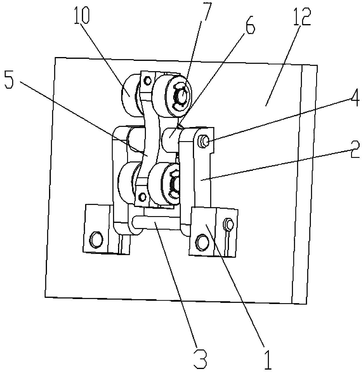
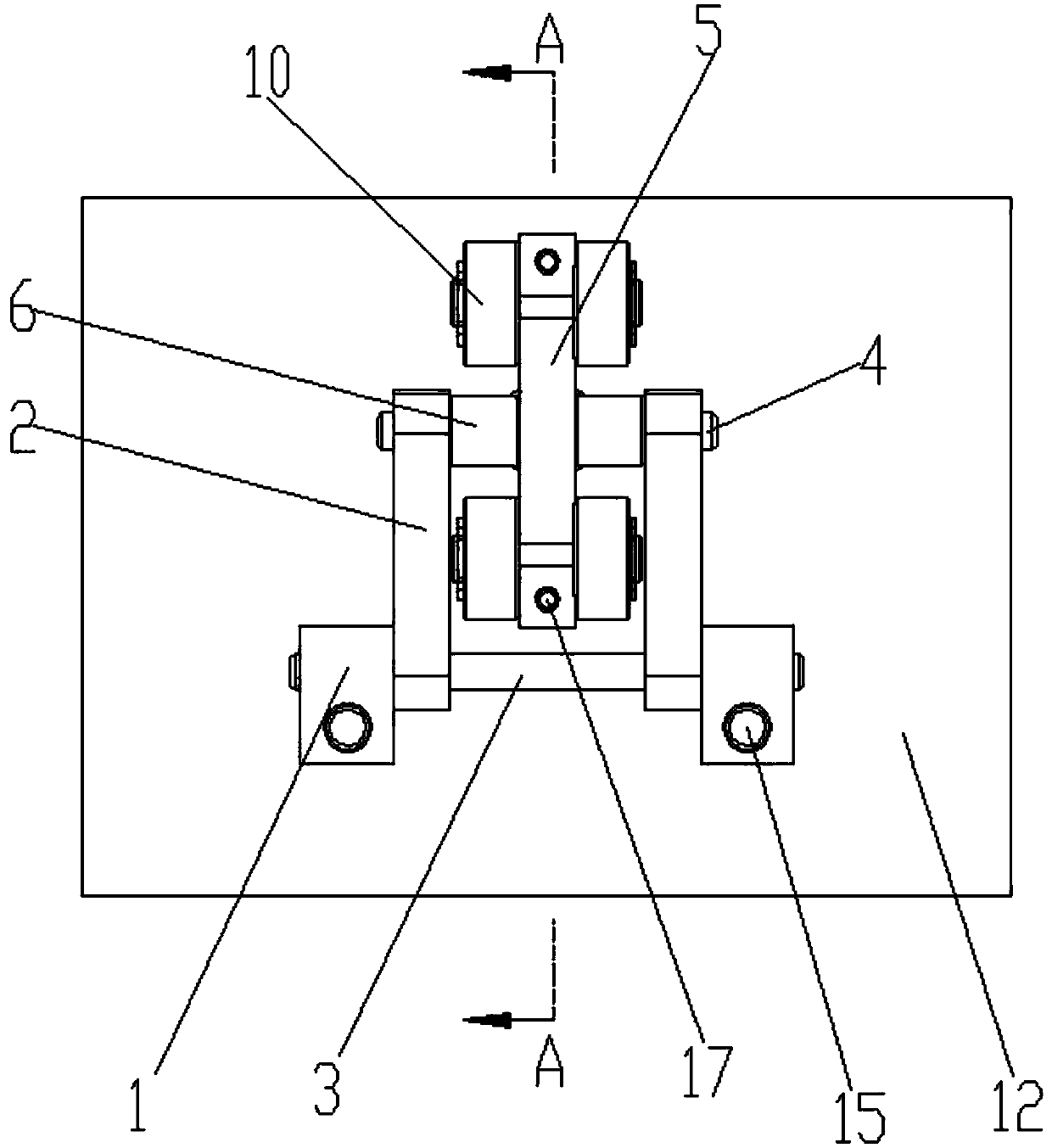
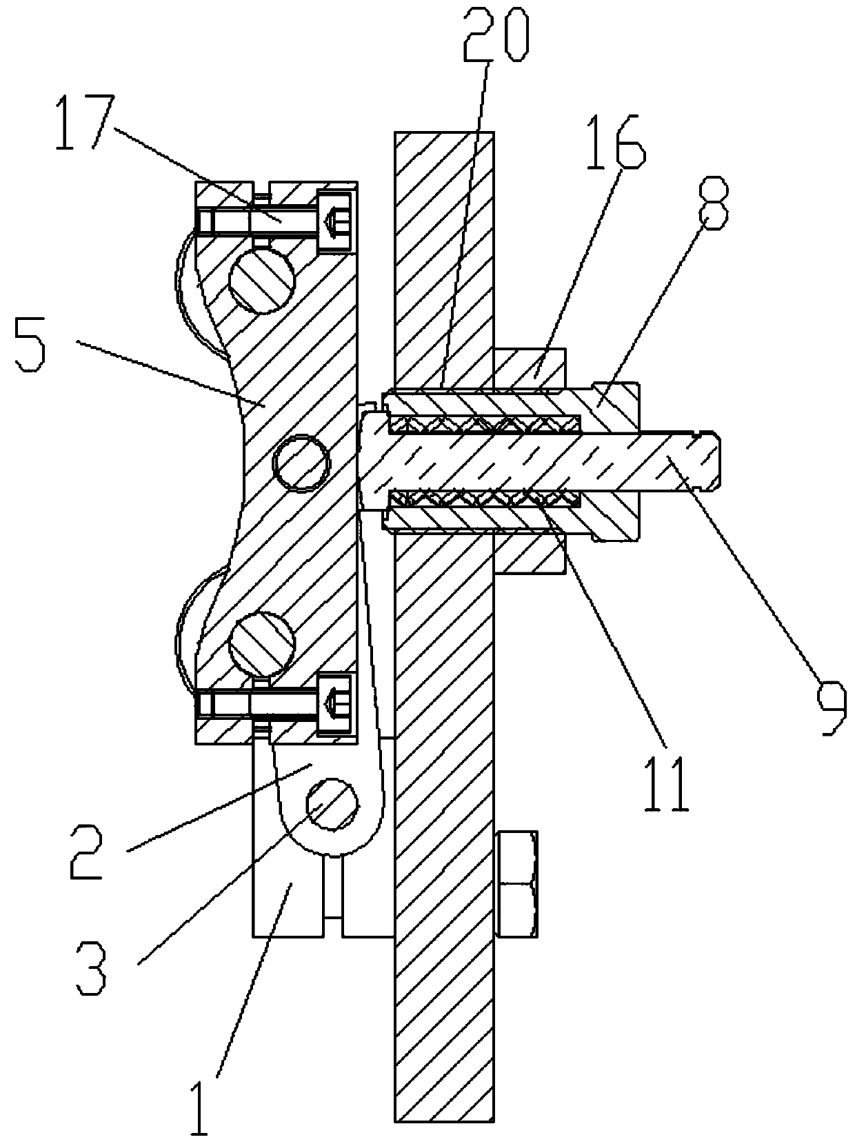
[0020] A pressurizing device, comprising a fixed plate 12, two fixed blocks 1 are arranged on the fixed plate 12, the two fixed blocks 1 are symmetrically arranged left and right, the fixed blocks 1 are fixed on the fixed plate 12 by bolts 15, the two fixed blocks 1 A fixed shaft 3 is installed between them, and two rocker arms 2 are arranged to rotate on the fixed shaft 3, and a rocker shaft 4 is installed on the end of the rocker arm 2 away from the fixed shaft 3, and a bearing bracket 5 is installed at the middle position of the rocker shaft 4, and the bearing bracket The frame 5 can rotate around the rocker shaft 4, and the rocker shaft 4 is covered with two sleeves 6, which are respectively located between the bearing bracket 5 and the two rocker arms 2, and the two ends of the bearing bracket 5 are equipped with roller shafts 7, and the rollers Both sides of the shaft 7...


PUM


Abstract

The invention discloses a pressurizing device. The pressurizing device comprises a fixed plate, wherein two fixed blocks are arranged on the fixed plate, bilaterally symmetric and fixed on the fixed plate through bolts; a fixed shaft is mounted between the two fixed blocks; two rocker arms are rotationally arranged on the fixed shaft; a rocking shaft is mounted at one end, away from the fixed shaft, of each rocker arm, and a bearing bracket is mounted in the middle of the rocking shaft and can rotate around the rocking shaft. The pressurizing device is simple in structure and convenient to use, a certain pressure is applied to one shaft, extra pressure besidesdead weight is produced between the shaft and the other shaft, so that pressure of fabric is increased, and drafting force of the fabric is increased.

Description

technical field [0001] The invention relates to the technical field of textile machinery, in particular to a pressurizing device. Background technique [0002] In textile machinery, in order to generate greater draft force for the fabric passing between two shafts, the general method is to increase the diameter of the shaft and use its own gravity to increase the pressure between the two shafts, thereby increasing the pressure on the fabric. Improve the drafting force of the fabric; some use springs at both ends of a shaft to increase the pressure between the two shafts by spring force, but this method can only increase the pressure at both ends of the shaft, and cannot increase the pressure at the center of the shaft. Contents of the invention [0003] The purpose of the present invention is to overcome the deficiencies of the prior art and provide a pressurizing device. [0004] To achieve the above object, the present invention provides the following technical solution...

Claims


Application Information

Patent Timeline
IPC IPC(8): D06C15/02
CPCD06C15/02
Inventor 陈宥融董炯
Owner 浙江泰坦股份有限公司
Learn More