
Fixing device, light source system and optical system

A technology of a fixing device and a light source system, applied in the optical field, can solve the problems of harsh processing accuracy requirements, insufficient reliability, and difficult assembly, and achieve the effects of easy disassembly and assembly, strong practicability, and stable and effective installation.

Active Publication Date: 2019-10-29
APPOTRONICS CORP LTD
View PDF5 Cites 0 Cited by
  • Summary
  • Abstract
  • Description
  • Claims
  • Application Information

AI Technical Summary

Problems solved by technology

[0003] At present, the optical lenses arranged at zero distance in the light source of 3LCD educational projectors on the market are often fixed and supported by a single pressing piece and the housing. This fixing method not only requires a more complicated housing bracket, but also requires relatively high processing accuracy. It is harsh, the processing cost is high, and the reliability of the two lenses fixed by only one shrapnel is not enough, and relative deviation may occur
In addition, there is another way of fixing is to fix by glue on the surface of the lens, so that on the one hand, the glue on the surface of the lens will more or less affect a part of the optical path and reduce the light effect; There is volatilization in the glass, which will pollute the lens, and the way of viscose is not easy to disassemble and difficult to assemble

Method used


Image

  • Fixing device, light source system and optical system
  • Fixing device, light source system and optical system
  • Fixing device, light source system and optical system

Examples


Embodiment Construction

[0036] In order to more clearly understand the above objects, features and advantages of the present invention, the present invention will be described in detail below in conjunction with the accompanying drawings and specific embodiments. It should be noted that, in the case of no conflict, the embodiments of the present application and the features in the embodiments can be combined with each other.

[0037] In the following description, many specific details are set forth in order to fully understand the present invention, and the described embodiments are only a part of the embodiments of the present invention, rather than all the embodiments. Based on the embodiments of the present invention, all other embodiments obtained by persons of ordinary skill in the art without making creative efforts belong to the protection scope of the present invention.

[0038] Unless otherwise defined, all technical and scientific terms used herein have the same meaning as commonly understo...


PUM


Abstract

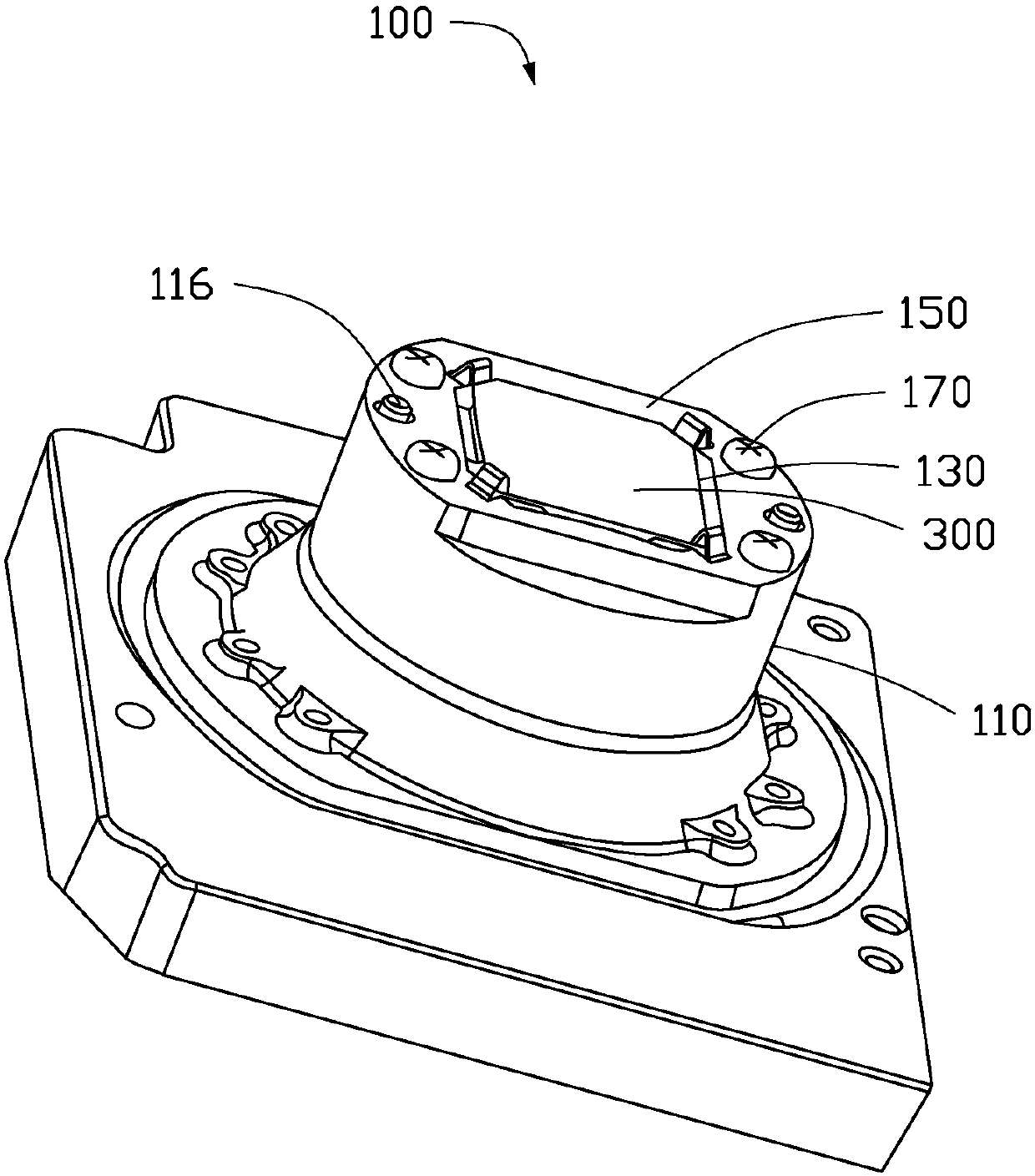
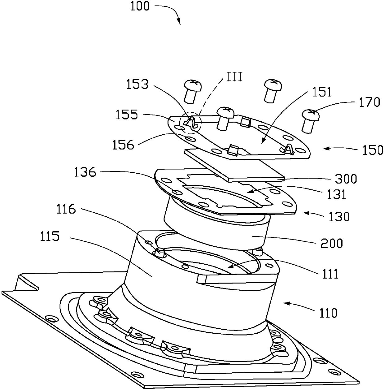
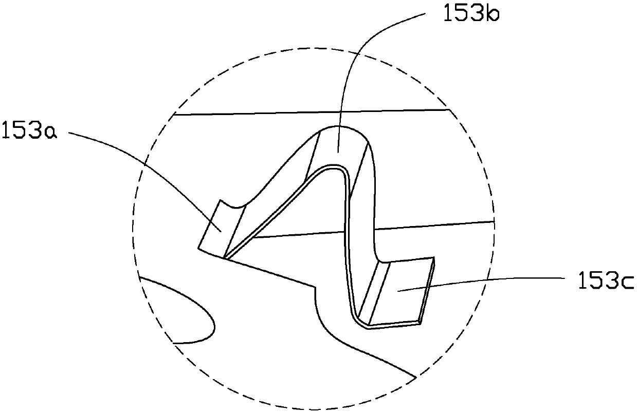
The invention provides a fixing device, a light source system and an optical system; the fixing device is used for fixing a first lens and a second lens and comprises a support, a first elastic sheetand a second elastic sheet which are sequentially stacked; the support is provided with an accommodating cavity, and the accommodating cavity is used for accommodating the first lens; the first elastic sheet is provided with a first through hole for accommodating the second lens; the second elastic sheet is provided with at least one abutting part, and the abutting part elastically abuts against the surface of the second lens. By using the fixing device, the first lens and the second lens can be fixed, and the first lens and the second lens can be reliably and tightly attached.

Description

technical field [0001] The invention relates to the field of optical technology, in particular to a fixing device, a light source system and an optical system. Background technique [0002] This section is intended to provide a background or context to a detailed description of the invention that is recited in the claims. The descriptions herein are not admitted to be prior art by inclusion in this section. [0003] At present, the optical lenses arranged at zero distance in the light source of 3LCD educational projectors on the market are often fixed and supported by a single pressing piece and the housing. This fixing method not only requires a more complicated housing bracket, but also requires relatively high processing accuracy. It is harsh, the processing cost is high, and the reliability of the two lenses fixed by only one shrapnel is not enough, and relative deviation may occur. In addition, there is another way of fixing is to fix by glue on the surface of the len...

Claims


Application Information

Patent Timeline
Patent Type & Authority Applications(China)
IPC IPC(8): G02B7/02G03B21/20
CPCG02B7/021G03B21/20G02B7/02F21V5/04
Inventor 周正平周建华李屹
Owner APPOTRONICS CORP LTD
Learn More