
Switch gear and rubber joints

A technology of switchgear and rubber joint, applied in the direction of electric switch, emergency protection device, emergency contact form, etc., can solve the problem of foreign matter entering the space between the second rubber dome and the base plate from flowing out of the second rubber dome, etc. problem, to achieve the effect of inhibiting the arrival of foreign objects

Active Publication Date: 2021-04-20
KK TOKAI RIKA DENKI SEISAKUSHO
View PDF13 Cites 0 Cited by
  • Summary
  • Abstract
  • Description
  • Claims
  • Application Information

AI Technical Summary

Problems solved by technology

Then, the foreign matter that may have entered between the rubber joint and the base plate does not flow toward the second rubber dome and reaches the second air passage, or the foreign matter that enters the space between the second rubber dome and the base plate passes through the second rubber dome. Top out

Method used


Image

  • Switch gear and rubber joints
  • Switch gear and rubber joints
  • Switch gear and rubber joints

Examples


Embodiment Construction

[0023] (Switch device according to embodiment of the present invention)

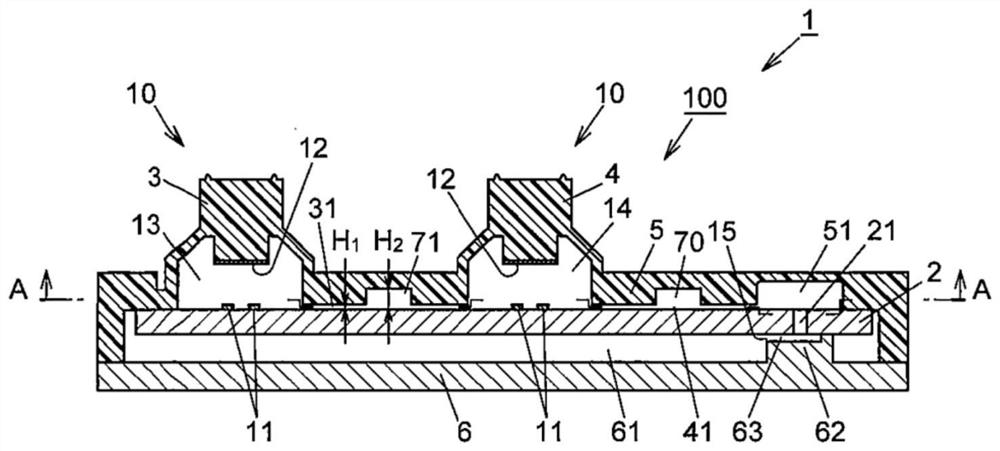
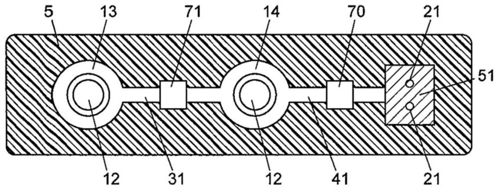
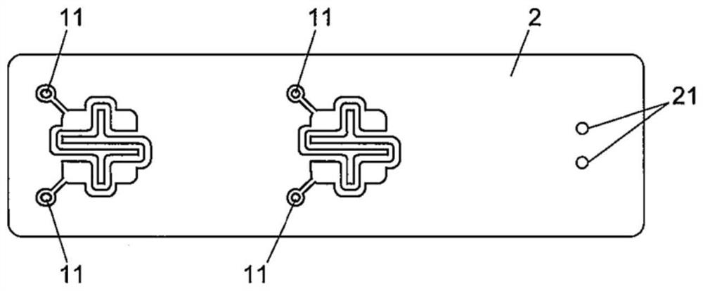
[0024] The switch device 1 according to the embodiment of the present invention is configured to include: a base plate 2 having at least one fixed contact 11 and an inflow and outflow portion provided with at least one through hole 21 through which a fluid passes; and a rubber joint covering the base plate 2 100, the rubber joint 100 has: movable contact parts 3, 4, which are at least one movable part disposed opposite to each of at least one fixed contact 11, and make the movable contacts corresponding to each of the fixed contacts 11 12 can be elastically deformed in a contact-separated manner; the venting cavity 51 as the inlet and outlet part is arranged opposite to the inflow and outflow part, and a space is formed between it and the inflow and outflow part; the air groove 41 as the flow path part, its Consists of a flow path connecting the venting cavity portion 51 and at least one movable contact ...


PUM


Abstract

The present invention provides a switchgear and a rubber joint capable of suppressing foreign matter from reaching contacts. The switch device is configured to include: a base plate having at least one fixed contact, and an inflow and outflow portion provided with at least one through hole through which fluid passes; and a rubber joint covering the base plate, the rubber joint having: a movable contact part, which is at least one movable part arranged opposite to each of at least one fixed contact, and elastically deforms the movable contact corresponding to each of the fixed contacts so as to be in contact with and separated from each other; the venting cavity as the entrance and exit part part, which is arranged opposite to the inflow and outflow part, and forms a space between it and the inflow and outflow part; the air groove as the flow path part, which constitutes a flow path connecting the venting cavity part and at least one movable contact part; and at least one cavity portion having a space larger than a space occupied by a representative length of the air groove at a part of the air groove and having strength to maintain the shape of the space thereof.

Description

technical field [0001] The invention relates to switchgear and rubber joints. Background technique [0002] The conventional switch device described in Patent Document 1 is a rubber plate covering one surface side of a substrate, and includes a first rubber dome, an air storage chamber, a second rubber dome, a first air passage, and a second air passage. [0003] The first rubber dome is a dome-shaped portion that covers the fixed contact and has a movable contact inside. An air storage chamber covers one end of the terminal. The second rubber dome is a dome-shaped portion located between the first rubber dome and the air storage chamber. The first air passage connects the inside of the first rubber dome with the inside of the second rubber dome. The second air passage connects the inside of the second rubber dome with the inside of the air storage chamber. The first rubber dome and the second rubber dome are configured to be pressed and operated by an operating member. ...

Claims


Application Information

Patent Timeline
Patent Type & Authority Patents(China)
IPC IPC(8): H01H13/06H01H13/10H01H13/14H01H13/36
CPCH01H13/06H01H13/10H01H13/14H01H13/36H01H13/82H01H2213/00H01H2213/014H01H13/52H01H2205/022H01H2227/022
Inventor 小川翔
Owner KK TOKAI RIKA DENKI SEISAKUSHO
Learn More