
Forming method for key caps

A molding method and key technology, which are applied to electrical components, electrical switches, circuits, etc., can solve the problems of time-consuming and laborious, the snap hook 106 of the key cap 101 is broken, and the manufacturing cost of the keyboard 1 is increased.

Active Publication Date: 2019-10-29
PRIMAX ELECTRONICS LTD
View PDF22 Cites 0 Cited by
  • Summary
  • Abstract
  • Description
  • Claims
  • Application Information

AI Technical Summary

Problems solved by technology

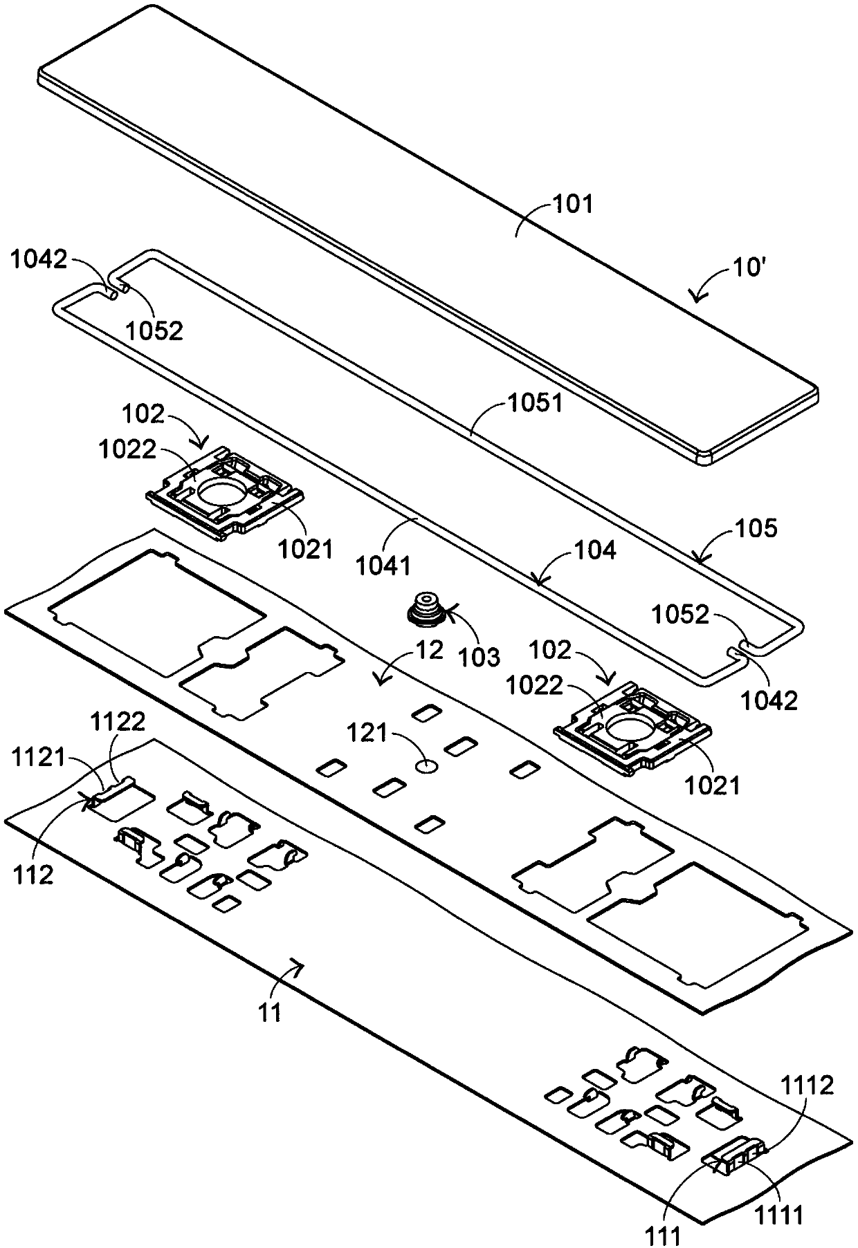
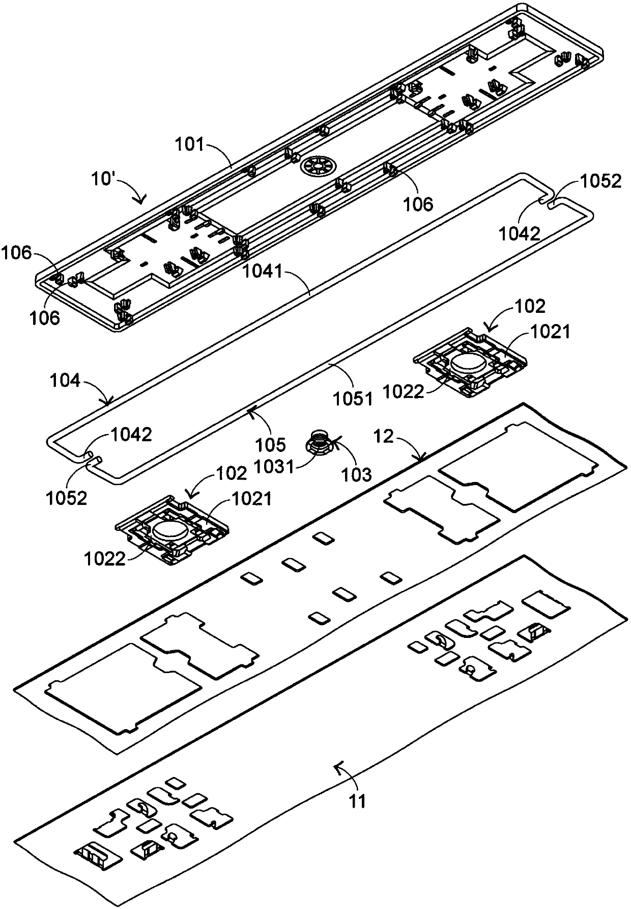
[0009] Although the first balance bar 104 and the second balance bar 105 have the above advantages, they also increase the manufacturing cost of the keyboard 1 because the first balance bar 104 and the second balance bar 105 must be assembled on the keycap 101.
Generally speaking, the assembly work of the first balance bar 104, the second balance bar 105 and the key cap 101 is manually performed by manpower, which is time-consuming and laborious, and the hook 106 of the key cap 101 is likely to be broken due to assembly errors.

Method used


Image

  • Forming method for key caps
  • Forming method for key caps
  • Forming method for key caps

Examples


Embodiment Construction

[0089] In view of the problems caused by the known technology, the present invention provides a method that can solve the known technical problem. First, the apparatus required for the method of the present invention will be described. Please also see Figure 5 as well as Figure 6 , Figure 5 In order to apply the first male mold of the present invention method, the second male mold and the structural representation of the female mold in a preferred embodiment, and Figure 6 It is a schematic view of the structure of the first male mold, the second male mold and the female mold applied to the method of the present invention from another perspective in a preferred embodiment. Figure 5 as well as Figure 6 It shows a first male mold 21, a second male mold 22, a female mold 23, a moving mechanism 24, a balance bar 3 and a key cap 4, wherein the balance bar 3 includes a first section 31 and a second section 32, and the key The cap 4 has a plurality of hooks 41 . The first ...


PUM


Abstract

The invention provides a forming method for key caps. The method includes fixing a balance rod on a first male mold; forming a key cap through a second male mold, a female mold and an injection molding technology; separating the second male mold and the female mold, and fixing the key cap on the female mold; overlapping the first male mold and the female mold so as to combine the balance rod and the key cap; and separating the first male mold and the female mold, and making the balance rod separate from the first male mold. Thus, the balance rod and the key cap can be assembled without utilizing manpower.

Description

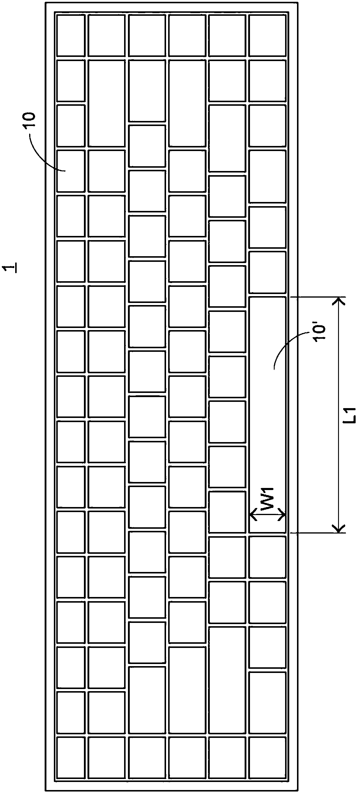
technical field [0001] The invention relates to a keyboard, in particular to a method for forming keycaps of the keyboard. Background technique [0002] Common computer peripheral input devices include a mouse, a keyboard, and a trackball. The keyboard can directly input text and symbols to the computer, so it is highly valued by users and input device manufacturers. The subject of the present invention is the keyboard. [0003] see figure 1 , which is a schematic diagram of the appearance structure of a known keyboard. The surface of the known keyboard 1 has a plurality of keys 10, 10', the key 10 is classified as a general-sized key, and the key 10' is classified as a longer-sized key. Wherein, the length of the key 10 is slightly greater than its width, and the length L1 of the key 10' is much greater than its width W1. A plurality of said keys 10, 10' are for the user to press with fingers to generate a corresponding signal to the computer, so that the computer execu...

Claims


Application Information

Patent Timeline
IPC IPC(8): H01H13/88
CPCH01H13/88H01H2229/044
Inventor 周以德李哲安
Owner PRIMAX ELECTRONICS LTD
Learn More