Clamping device
A clamping device and clip technology, applied in the field of medical devices, can solve the problems of ligation failure, easy loosening, secondary injury, etc.
- Summary
- Abstract
- Description
- Claims
- Application Information
AI Technical Summary
Problems solved by technology
Method used
Image

Examples
Embodiment 1
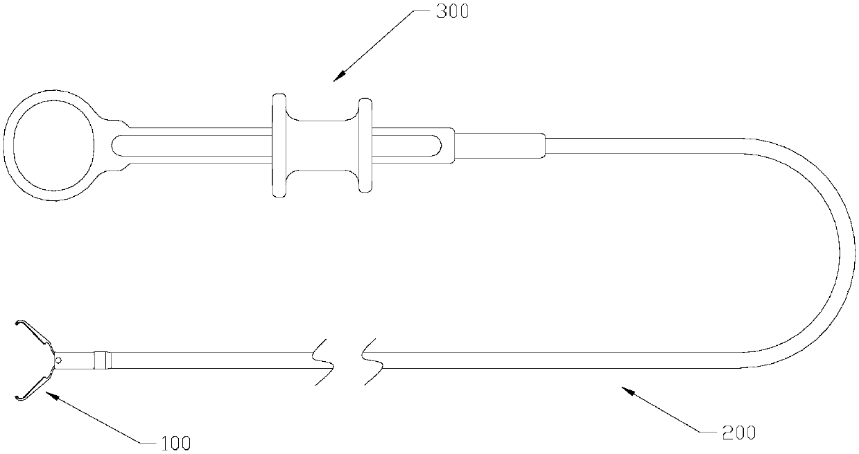
[0077] Such as Figures 1 to 12 As shown, the clamping device includes a clip 100, a sheath tube 200, a control part 300, a tightening tube 140 and a mandrel 400, the mandrel 400 is passed through the sheath tube 200, and the mandrel 400 passes through the tightening tube 140 and the clip 100 Docking, the control part 300 is docked with the sheath tube 200 and the mandrel 400 respectively. During the operation, the clip 100, the tightening tube 140 and a part of the sheath tube 200 are inserted into the endoscope channel, and the core can be pulled proximally by operating the control part 300 The shaft 400 can either push the mandrel 400 to move distally, or lock the relative position of the mandrel and the sheath tube 200 .
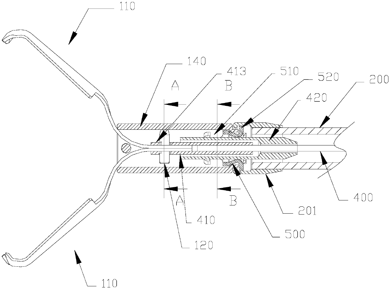
[0078] Such as figure 2 As shown, the distal end of the sheath tube 200 is provided with a connecting cap 201 , the connecting cap 201 has a channel, the channel of the connecting cap 201 communicates with the channel of the sheath tube 200 , and the i...
Embodiment 2
[0093] The difference between embodiment one and embodiment two is:
[0094] Such as Figure 13 , 14 As shown, the hooking sleeve 500 is not provided, and the inner wall of the tightening tube 140 is provided with a groove as a locking position 510. When the clip 100 is in the second position, the locking part 121 of the locking pin 120 extends into the tightening tube 140. Lock in the groove (lock position 510).
[0095] or, as in Figure 15 , 16 As shown, the side wall of the tightening tube 140 is provided with four openings as locking positions 510. When the clip 100 is in the second position, the locking portion 121 of the locking pin 120 extends into the openings of the tightening tube 140 (locking position 510). 510) internal lock. There may be one or more holes as the locking position 510 .
[0096] or, as in Figure 17 , 18 As shown, two slots are provided on the side wall of the tightening tube 140 as locking positions 510. When the clip 100 is in the second ...
Embodiment 3
[0098] The difference between embodiment three and embodiment one is:
[0099] Such as Figures 19 to 23 As shown, the locking pin 120 includes two locking caps 130, one end of the two locking caps 130 is nested with each other, and the other end is a locking portion 121, as Figure 21 , 22 As shown, one of the locking caps 130 is set outside the other locking cap 130 at this time, and the two locking caps 130 are in the shape of "one", and an elastic member 131 is arranged between the two locking caps 130 as the elastic part 122. Among them, the elastic member 131 is arranged in the channel of the locking cap 130 (but not limited thereto, it can also be arranged outside the locking cap 130). The two ends of the elastic member 131 are connected to the two locking caps 130 respectively. Pressing the locking cap 130 inwardly can compress the elastic member 131 , and the locking cap 130 will rebound under the elasticity of the elastic member 131 when the elastic member 131 is r...
PUM
 Abstract
Description
Claims
Application Information
 - R&D
- Intellectual Property
- Life Sciences
- Materials
- Tech Scout
- Unparalleled Data Quality
- Higher Quality Content
- 60% Fewer Hallucinations
Browse by: Latest US Patents, China's latest patents, Technical Efficacy Thesaurus, Application Domain, Technology Topic, Popular Technical Reports.
© 2025 PatSnap. All rights reserved.Legal|Privacy policy|Modern Slavery Act Transparency Statement|Sitemap|About US| Contact US: help@patsnap.com