
Blending device for housekeeping detergent

A cleaning agent and housekeeping technology, which is applied in the field of preparation devices for cleaning agents in housekeeping services, can solve the problems of poor reliability, low practicability, and inability to mix the mixture conveniently and uniformly, and achieve smooth rotation, enhanced practicability, and convenient rotation without longitudinal rotation The effect of moving

Inactive Publication Date: 2019-11-01
盐城盐西幸福产业发展有限公司
View PDF4 Cites 3 Cited by
  • Summary
  • Abstract
  • Description
  • Claims
  • Application Information

AI Technical Summary

Problems solved by technology

[0002] As we all know, the cleaning agent preparation device for housekeeping service is an auxiliary device used to prepare cleaning agent in the process of housekeeping service to make it better for subsequent use, and it has been widely used in the field of cleaning agent preparation; The existing cleaning agent preparation device for housekeeping service includes a bottom plate and a working box. The working box is installed on the top of the bottom plate. There is a working cavity inside the working box. A cover is installed, and a discharge pipe is sealed and connected to the lower part of the front side of the working box, and a discharge valve is arranged on the discharge pipe; The raw materials are all introduced into the working chamber, allowed to stand and mix, and the mixture can be discharged through the unloading pipe; it is found in the use of the existing cleaning agent preparation device for housekeeping that the mixture cannot be conveniently mixed evenly, thus As a result, its use reliability is poor and its practicability is low

Method used


Image

  • Blending device for housekeeping detergent
  • Blending device for housekeeping detergent
  • Blending device for housekeeping detergent

Examples


Embodiment Construction

[0018] The specific implementation manners of the present invention will be further described in detail below in conjunction with the accompanying drawings and embodiments. The following examples are used to illustrate the present invention, but are not intended to limit the scope of the present invention.

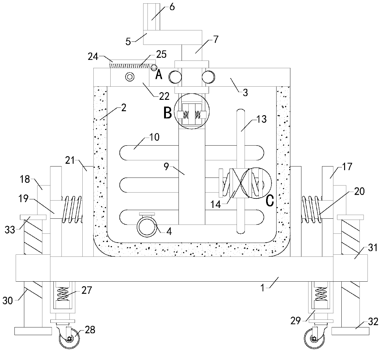
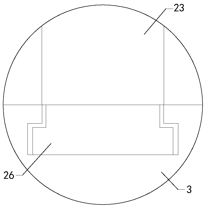
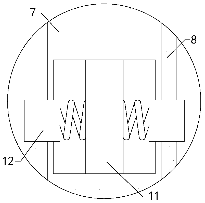
[0019] Such as Figure 1 to Figure 4 As shown, a preparation device for housekeeping service cleaning agent of the present invention includes a base plate 1 and a working box 2, a working chamber is arranged inside the working box 2, and a feeding maintenance port is connected to the top of the working box 2, and the feeding maintenance The opening cover is equipped with a cover 3, and the lower part of the front side of the working box 2 is sealed and connected with a discharge pipe 4, and a discharge valve is arranged on the discharge pipe 4; it also includes a fixed shaft 5, a handle 6, a plug post 7, a plug Pipe 8, connecting column 9 and multiple sets of stirring rod...


PUM


Abstract

The invention relates to the technical field of auxiliary devices and in particular to a blending device for a housekeeping detergent. Mixtures of the blending device can be conveniently and uniformlymixed, so that the use reliability and the practicability of the blending device can be improved. The blending device comprises a bottom plate, a working tank as well as a fixing shaft, a handle, aninsertion column, an insertion tube, a connecting column, a plurality groups of stirring rods, a limiting column, two groups of limiting springs and two groups of positioning blocks, wherein a workingcavity is formed in the working tank; a feeding maintenance hole is formed in the top end of the working tank in a communicating manner; a baffle cover is mounted at the feeding maintenance hole in acovering manner; a discharge tube is in sealed communicating below the front side of the working tank; a discharge valve is arranged on the discharge tube; a limiting cavity is formed in the lower part inside the insertion column; a left through hole and a right through hole are formed in the left side wall and the right side wall of the insertion column; a left limiting hole and a right limitinghole are respectively formed in the left side wall and the right side wall of the insertion tube; a through groove is formed in the middle of the baffle cover in a communicating manner; a bead groupis rotationally fixed in the inner side wall of the through groove; and two groups of fixing rings are fixedly arranged on the outer side of the insertion column in a sleeving manner.

Description

technical field [0001] The invention relates to the technical field of accessory devices, in particular to a preparation device for housekeeping service cleaning agents. Background technique [0002] As we all know, the cleaning agent preparation device for housekeeping service is an auxiliary device used to prepare cleaning agent in the process of housekeeping service to make it better for subsequent use, and it has been widely used in the field of cleaning agent preparation; The existing cleaning agent preparation device for housekeeping service includes a bottom plate and a working box. The working box is installed on the top of the bottom plate. There is a working cavity inside the working box. A cover is installed, and a discharge pipe is sealed and connected to the lower part of the front side of the working box, and a discharge valve is arranged on the discharge pipe; The raw materials are all introduced into the working chamber, allowed to stand and mix, and the mix...

Claims


Application Information

Patent Timeline
Patent Type & Authority Applications(China)
IPC IPC(8): B01F7/18
CPCB01F27/191B01F27/90B01F2101/24
Inventor 徐加峰金斌张一鹭
Owner 盐城盐西幸福产业发展有限公司
Learn More