Mounting structure and device
A technology of installation structure and installation frame, which is applied in the field of compressors, can solve problems such as vibration damping wear or breakage, affecting the impact resistance of compressors, and shortening the service life of vibration damping pads, so as to improve vibration resistance, prolong service life, and improve reliability. sexual effect
- Summary
- Abstract
- Description
- Claims
- Application Information
AI Technical Summary
Problems solved by technology
Method used
Image
Examples
Embodiment 2
[0115] Figure 12 to Figure 17 The structure of Embodiment 2 of the installation structure of the present invention is shown. The difference between the installation structure of Embodiment 2 and Embodiment 1 lies in the shapes of the upper boss and the sink hole. In the second embodiment, the upper boss 42 is in the shape of a square prism, the sink hole 32 is in a square shape, and the mounting hole 51 is in a square shape. The lower damping pad will not rotate relative to the mounting plate, so the gap e will be more uniform.
[0116] In this embodiment, the length of the bottom side of the upper boss 42 is L1, and the length of the long side of the lower vibration damping pad is Lb, where L1=Lb / 3.
[0117] In this embodiment, the side length of the sinking hole 32 is L2, and the side length of the installation hole 51 is L3, where L3=L2=L1.
Embodiment 3
[0119] Figure 18 to Figure 21 The structure of the third embodiment of the mounting structure of the present invention is shown. The difference between the mounting structure of the third embodiment and the second embodiment is that the positions of the boss and the counterbore are different. In the third embodiment, the upper vibration-damping pad 30 The lower surface is provided with a lower boss 33, and the upper surface of the lower damping pad 40 has an upper counterbore 43 that cooperates with the lower boss 33. The portion between the lower surfaces of 30 forms a mounting body.
[0120] In this embodiment, the upper counterbore is square, the side length of the upper counterbore is L2, and the long side length of the lower vibration-damping pad is Lb, wherein L2=Lb / 3. The side length of the lower boss 33 is L1, and L2=L1.
[0121] In this embodiment, the height of the lower boss 33 is h1, the depth of the upper counterbore 43 is h2, and in the axial direction of the ...
Embodiment 4
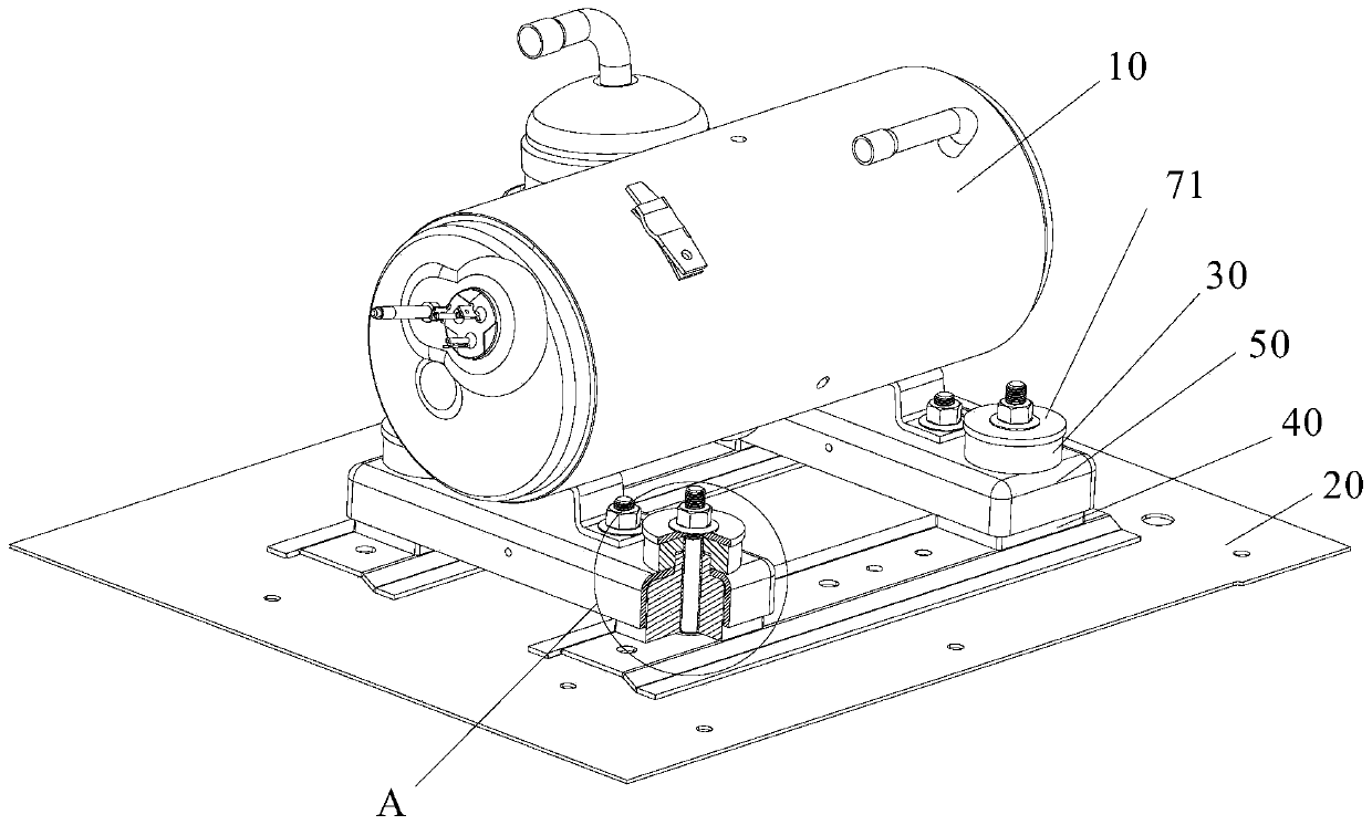
[0124] Figure 22 to Figure 26The structure of Embodiment 4 of the installation structure of the present invention is shown. The difference between the installation structure of Embodiment 4 and Embodiment 1 lies in the structure of the vibration-damping pad. In Embodiment 4, the upper vibration-damping pad 30 has an upper through hole 31 passing through its upper and lower surfaces, the lower vibration-damping pad 40 has a lower through-hole 41 passing through its upper and lower surfaces, and the vibration-damping pad also has an upper through hole 31 and a The vibration-damping sleeve 60 in the lower through hole 41 and the part of the vibration-damping sleeve 60 between the upper surface of the lower vibration-damping pad 40 and the lower surface of the upper vibration-damping pad 30 form an installation body. Compared with the vibration-damping pad in Embodiment 1, the vibration-damping pad removes the boss and the counterbore, the manufacturing process is simpler, the qu...
PUM
 Abstract
Description
Claims
Application Information
 - R&D
- Intellectual Property
- Life Sciences
- Materials
- Tech Scout
- Unparalleled Data Quality
- Higher Quality Content
- 60% Fewer Hallucinations
Browse by: Latest US Patents, China's latest patents, Technical Efficacy Thesaurus, Application Domain, Technology Topic, Popular Technical Reports.
© 2025 PatSnap. All rights reserved.Legal|Privacy policy|Modern Slavery Act Transparency Statement|Sitemap|About US| Contact US: help@patsnap.com


