Coupling with rotational angle

A coupling and rotating shaft technology, applied in the field of angularly rotatable couplings, can solve the problems of low efficiency, inability to switch freely, cumbersome and complicated, etc., and achieve the effects of safe and rapid process, sensitive response and simple operation.

Active Publication Date: 2019-11-01
江苏骏森工程机械有限公司
View PDF4 Cites 0 Cited by
  • Summary
  • Abstract
  • Description
  • Claims
  • Application Information

AI Technical Summary

Problems solved by technology

[0002] As we all know, the coupling is one of the commonly used components in the mechanical field. The main function of the coupling is to connect two independent rotating shafts together so that the kinetic energy can be transmitted to each other. It is generally used to connect the driving shafts in different mechanisms. It is a mechanical component that is firmly connected with the driven shaft and rotates together, and transmits motion and torque. Couplings are more and more widely used in the mechanical field. Although there are many types of couplings at this stage, they are all in two independent shaft systems. On the basis of this, when three or more shafts are required to cooperate to generate power transmission, it is often impossible to solve or to carry out more cumbersome and complicated processing. The efficiency is low and it cannot be switched freely. There is a lack of couplings that can cooperate with multiple shafts on the market. Therefore, it is necessary to design an angularly rotatable coupling to solve the above problems

Method used


Image

  • Coupling with rotational angle
  • Coupling with rotational angle
  • Coupling with rotational angle

Examples


Embodiment Construction

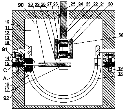
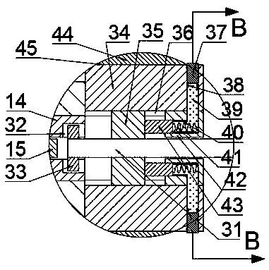
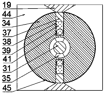
[0023] Combine below Figure 1-4 The present invention is described in detail, and for convenience of description, the orientations mentioned below are now stipulated as follows: figure 1 The up, down, left, right, front and back directions of the projection relationship itself are the same.

[0024] combined with Figure 1-4 The angularly rotatable coupling includes a fuselage 10, the fuselage 10 includes a power chamber 11, and the power chamber 11 is provided with a transmission mechanism 90 that drives the driven shaft to move by connecting with the driving shaft , the top of the power chamber 11 is fixed with a first through hole 24, the first through hole 24 is provided with a first rotating shaft 25, the first rotating shaft 25 is provided with a second rotating shaft 23, and the first rotating shaft 25 is provided with a second rotating shaft 23. The front and rear ends of the two rotating shafts 23 are symmetrically fixedly connected with first support blocks 22, an...


PUM


Abstract

The invention discloses a coupling with a rotational angle. The coupling with the rotational angle comprises a machine body, the machine body comprises a power cavity, a transmission mechanism which is connected with driving shafts and drives a driven shaft to move is arranged in the power cavity, a first through hole is fixedly formed in the top end of the power cavity, a first rotating shaft isarranged in the first through hole in a rotating mode, and a second rotating shaft is rotationally arranged in the first rotating shaft. According to the coupling, three shafting are firstly fixed onthe coupling, when random one driving shaft of two driving shafts rotates, the driving shaft can drive the driven shaft to rotate, the driven shaft can be automatically connected with the driving shafts by utilizing the rotation of the kinetic energy by the coupling, so that the driven shaft can be connected with the driving shafts to transmit power, the coupling is complete in function and sensitive in reaction, the coupling is selected and connected in a full-automatic mode in the stage of selecting and connecting the moving rotating shafts, the working efficiency of the process is high, andthe coupling has high integration degree.

Description

technical field [0001] The invention relates to the field of mechanical kinetic energy transmission, in particular to an angularly rotatable coupling. Background technique [0002] As we all know, the coupling is one of the commonly used components in the mechanical field. The main function of the coupling is to connect two independent rotating shafts together so that the kinetic energy can be transmitted to each other. It is generally used to connect the driving shafts in different mechanisms. It is a mechanical component that is firmly connected with the driven shaft and rotates together, and transmits motion and torque. Couplings are more and more widely used in the mechanical field. Although there are many types of couplings at this stage, they are all in two independent shaft systems. On the basis of this, when three or more shafts are required to cooperate to generate power transmission, it is often impossible to solve or to carry out more cumbersome and complicated pr...

Claims


Application Information

Patent Timeline
IPC IPC(8): F16D3/16
CPCF16D3/16
Inventor 杨明华
Owner 江苏骏森工程机械有限公司
Why Eureka
Try Eureka