Unlock instant, AI-driven research and patent intelligence for your innovation.

Automatic external thread detection device and detection method

A detection device and external thread technology, which is applied in the field of automatic external thread detection devices, can solve the problems of low detection efficiency and a large amount of manual labor, and achieve the effects of wide application, convenient operation, and reliable positioning and clamping

Active Publication Date: 2019-11-01
HEILONGJIANG UNIV
View PDF8 Cites 0 Cited by
  • Summary
  • Abstract
  • Description
  • Claims
  • Application Information

AI Technical Summary

Problems solved by technology

[0002] Thread detection is an important task after thread processing, and it is also an important basis for evaluating the quality of threads. The existing thread detection device needs workers or mechanical transmission to transport the threaded pipe to the corresponding detection position, and then Manually clamp the workpiece and use inspection tools to inspect the threaded pipe. The process requires a lot of manual labor and the inspection efficiency is low.

Method used


Image

  • Automatic external thread detection device and detection method
  • Automatic external thread detection device and detection method
  • Automatic external thread detection device and detection method

Examples


Embodiment 1

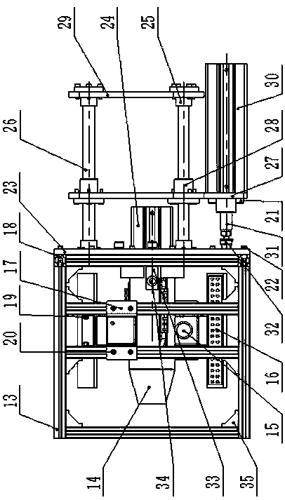
[0026] An automatic external thread detection device, which is composed of: a rear fixing plate 29, the rear fixing plate is respectively connected with three linear optical axes 26 through an optical axis support seat 25, and the linear optical axis passes through the movable connecting plate 27 is connected with the fixed plate 23, the movable connecting plate is connected with the push cylinder 30 through the bolt A21, and the push cylinder is connected with the floating connector 32 through the mandrel 31 at the front end, and the floating connector is fixed on the A locking cylinder 24 is installed on the right side of the middle position of the fixing plate, and the left side is connected with the three-claw fixing assembly 14. The fixing plate and the cube frame 13 are connected by bolts B22, and the cube frame Two CCD camera brackets 17 are respectively connected to the above, and the CCD camera brackets are respectively installed with a CCD camera 15 and a CCD strip li...

Embodiment 2

[0028] According to the automatic external thread detection device described in Embodiment 1, the movable connecting plate is connected with the linear optical axis through the bearing 28, the fixed plate is connected with the flange on the positioning sleeve 1, and the A limit block 12 is installed on the positioning sleeve, the front end of the positioning sleeve is connected with the guide cone 10 through threads, and the flange on the positioning sleeve is connected to the proximity switch 34 through the switch bracket 33, and the lock The tightening cylinder mandrel 8 is connected with the guide mandrel 11, the right side of the outer circle of the guide mandrel is connected with the movable three claws 6, and the outer left side of the guide mandrel is sleeved with a middle spacer 5, and the two ends of the middle spacer are respectively connected with three claws. The claw internal fixed plate 2, wherein each of the three-claw internal fixed plates is respectively connec...

Embodiment 3

[0030] According to the automatic external thread detection device described in Embodiment 2, the positioning sleeve is evenly provided with three elongated holes, the CCD camera bracket and the cube frame are connected by bolts D20 and T-nuts 18, the CCD camera bracket is There are two elongated holes on the upper side of the camera bracket, and the CCD camera bracket and the CCD camera are connected by bolts 19 .


PUM


Abstract

The invention relates to an automatic external thread detection device and a detection method. For the existing thread detection device, a threaded pipe is conveyed to a corresponding detection position by a worker or a mechanical transmission mode, a workpiece is clamped manually, a detection tool is used for detecting the threaded pipe, and the detection efficiency is low. The device in the invention comprises a rear fixed plate (29), the rear fixed plate is respectively connected with three linear optical axes (26) through optical axis support seats (25), the linear optical axes penetrate through a movable connecting plate (27) and are connected with a fixed plate (23), the movable connecting plate is connected with a push air cylinder (30) through a bolt A (21), the push air cylinder is connected with the floating connector (32) through a mandrel (31) at the front end, the floating connector is fixed on the fixed plate, a locking air cylinder (24) is installed on the right side ofthe middle position of the fixed plate, the left side of the fixed plate is connected with a three-jaw fixing assembly (24), and the fixed plate is connected with a cubic frame (13) through a bolt B (22). The detection method in the invention is used for the automatic external thread detection device.

Description

Technical field: [0001] The invention relates to an automatic external thread detection device and a detection method. Background technique: [0002] Thread detection is an important work that needs to be done after thread processing, and it is also an important basis for evaluating the quality of the thread. The existing thread detection device requires workers or mechanical transmission to transport the threaded pipe to the corresponding detection position, and then Manually clamping the workpiece and inspecting the threaded pipe with inspection tools requires a lot of manual labor, and the inspection efficiency is low. Invention content: [0003] The purpose of the present invention is to provide an automatic external thread detection device and detection method. When the device senses the threaded pipe to be tested, it automatically stops the movement and fixes and clamps it, and uses a CCD camera to shoot the workpiece and transmit the photo to the upper position. Th...

Claims


Application Information

Patent Timeline
Patent Type & Authority Applications(China)
IPC IPC(8): G01B11/24G01B11/26G01B11/14G01B11/06
CPCG01B11/0608G01B11/14G01B11/2425G01B11/26
Inventor 石勇时新
Owner HEILONGJIANG UNIV