
A high-speed permanent magnet motor rotor with integrated shaft sleeve and assembly method

A permanent magnet motor and assembly method technology, applied in the direction of magnetic circuit rotating parts, magnetic circuit shape/style/structure, etc., can solve the problems affecting the stability of the motor rotor structure and the decrease of the overall rigidity of the rotor, etc.

Active Publication Date: 2021-09-10
HARBIN DONGAN ENGINE GRP
View PDF9 Cites 1 Cited by
  • Summary
  • Abstract
  • Description
  • Claims
  • Application Information

AI Technical Summary

Problems solved by technology

[0002] The rotor of a general high-speed permanent magnet motor adopts an independent straight cylindrical protective sleeve to fasten the magnetic steel and other structures. When the motor is running at a high speed, due to the centrifugal force, there is a possibility that the protective sleeve and the magnetic steel will be separated, resulting in a decrease in the overall rigidity of the rotor. , affecting the structural stability of the motor rotor

Method used


Image

  • A high-speed permanent magnet motor rotor with integrated shaft sleeve and assembly method
  • A high-speed permanent magnet motor rotor with integrated shaft sleeve and assembly method
  • A high-speed permanent magnet motor rotor with integrated shaft sleeve and assembly method

Examples


Embodiment Construction

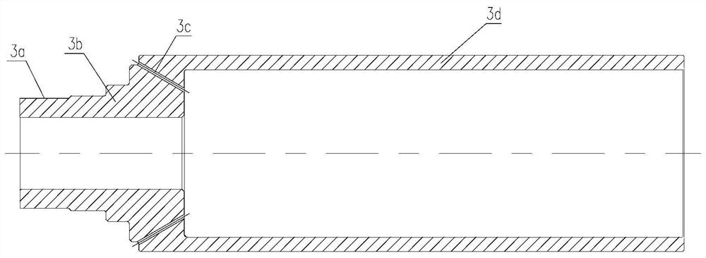
[0013] Detailed description: The rotor of a high-speed permanent magnet motor is as attached figure 1 As shown, it is composed of a lock nut 1, a disc spring 2, a shaft sleeve 3, a magnetic steel end cover 4, a magnetic steel 5, and a mandrel 6, and the structure is simple. First, assemble the magnetic steel 5 on the mandrel 6, apply adhesive on the joint surface, and then assemble the magnetic steel end cover 4 on the mandrel 6, so that the The right end surface of the magnetic steel end cover 4 is bonded to the left end surface of the magnetic steel 5, and the joint surface is coated with adhesive to form a combination. Then, the shaft sleeve 3 is heated and fitted on the outside of the assembly, and an interference fit is used between the shaft sleeve 3 and the assembly. Finally, install the disc spring 2 and lock nut 1 in turn on the left end of the mandrel 6, and during the process of tightening the lock nut 1, the disc spring 2 will generate a certain amount of compress...


PUM


Abstract

The invention belongs to the technical field of motors, and relates to a high-speed permanent magnet motor rotor with an integrated shaft sleeve and an assembly method. It includes a shaft sleeve (3), a magnetic steel end cover (4), a magnetic steel (5), and a mandrel (6); the present invention adopts a structure in which the protective sleeve and the shaft sleeve are integrated, which effectively provides the rigidity of the motor rotor, and at the same time, The mandrel passes through the shaft sleeve, and the axial pre-tightening force is ensured by the lock nut, so that the magnetic steel assembled between the shaft sleeve and the mandrel can be constrained by the axial force. When the motor is running at a high speed, due to the existence of the axial preload, the overall rigidity of the rotor can be effectively improved, thereby improving the structural stability of the motor rotor. In the present invention, the protection sleeve and the mandrel at one end are combined into one structure, which improves the rigidity of the rotor. At the same time, the mandrel at the other end acts as a pull rod, and the axial pre-tightening force is effectively guaranteed through the lock nut without Additional parts need to be added, the structure is simple, and the reliability is high.

Description

technical field [0001] The invention belongs to the technical field of motors, and relates to a high-speed permanent magnet motor rotor, in particular to a high-speed permanent magnet motor rotor with an integrated shaft sleeve and an assembly method. Background technique [0002] The rotor of a general high-speed permanent magnet motor adopts an independent straight cylindrical protective sleeve to fasten the magnetic steel and other structures. When the motor is running at a high speed, due to the centrifugal force, there is a possibility that the protective sleeve and the magnetic steel will be separated, resulting in a decrease in the overall rigidity of the rotor. , affecting the structural stability of the motor rotor. Contents of the invention [0003] Purpose of the present invention: the present invention adopts the integrated structure of the protective sleeve and the shaft sleeve, which effectively provides the rigidity of the motor rotor. The magnetic steel be...

Claims


Application Information

Patent Timeline
Patent Type & Authority Patents(China)
IPC IPC(8): H02K1/27H02K1/28
CPCH02K1/27H02K1/28
Inventor 王永恒耿加民刘丛红吕亚洲胡双雪何民潘振宇万思博王舒仝云峰
Owner HARBIN DONGAN ENGINE GRP
Learn More