
A miniature motor and method for assembling its shell and end cover

A technology of micro motors and assembly methods, applied in the direction of electromechanical devices, manufacturing motor generators, electrical components, etc.

Active Publication Date: 2020-07-28
温岭市凯仕达电机有限公司
View PDF1 Cites 0 Cited by
  • Summary
  • Abstract
  • Description
  • Claims
  • Application Information

AI Technical Summary

Problems solved by technology

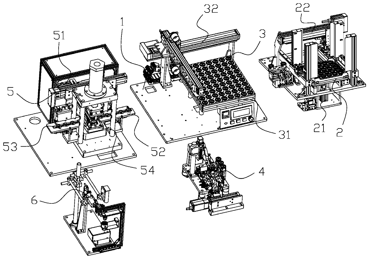
[0004] The purpose of the present invention is to solve the above-mentioned existing micro-motor assembly problems, to provide an automatic feeding of the shell through the shell feeding device; to automatically heat and dry the glue through the heating device; to automatically measure the amplitude through the amplitude measuring device; The shell and the end cover are assembled automatically by the press-in device; the assembly method of the micro motor shell and the end cover is automatically detected by the detection device

Method used


Image

  • A miniature motor and method for assembling its shell and end cover
  • A miniature motor and method for assembling its shell and end cover
  • A miniature motor and method for assembling its shell and end cover

Examples


Embodiment Construction

[0030] The following will clearly and completely describe the technical solutions in the embodiments of the present invention with reference to the accompanying drawings in the embodiments of the present invention. Obviously, the described embodiments are only some, not all, embodiments of the present invention.

[0031] In describing the present invention, it should be understood that the terms "upper", "lower", "front", "rear", "left", "right", "top", "bottom", "inner", " The orientation or positional relationship indicated by "outside" and so on is based on the orientation or positional relationship in the drawings, which is only for the convenience of describing the present invention and simplifying the description, rather than indicating or implying that the device or element referred to must have a specific orientation, or in a specific orientation construction, operation, and therefore should not be construed as limiting the invention.

[0032] Such as figure 1 As show...


PUM


Abstract

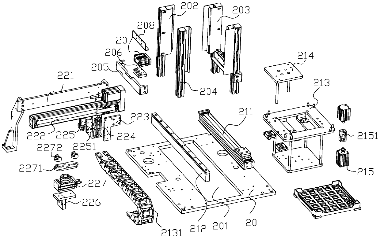
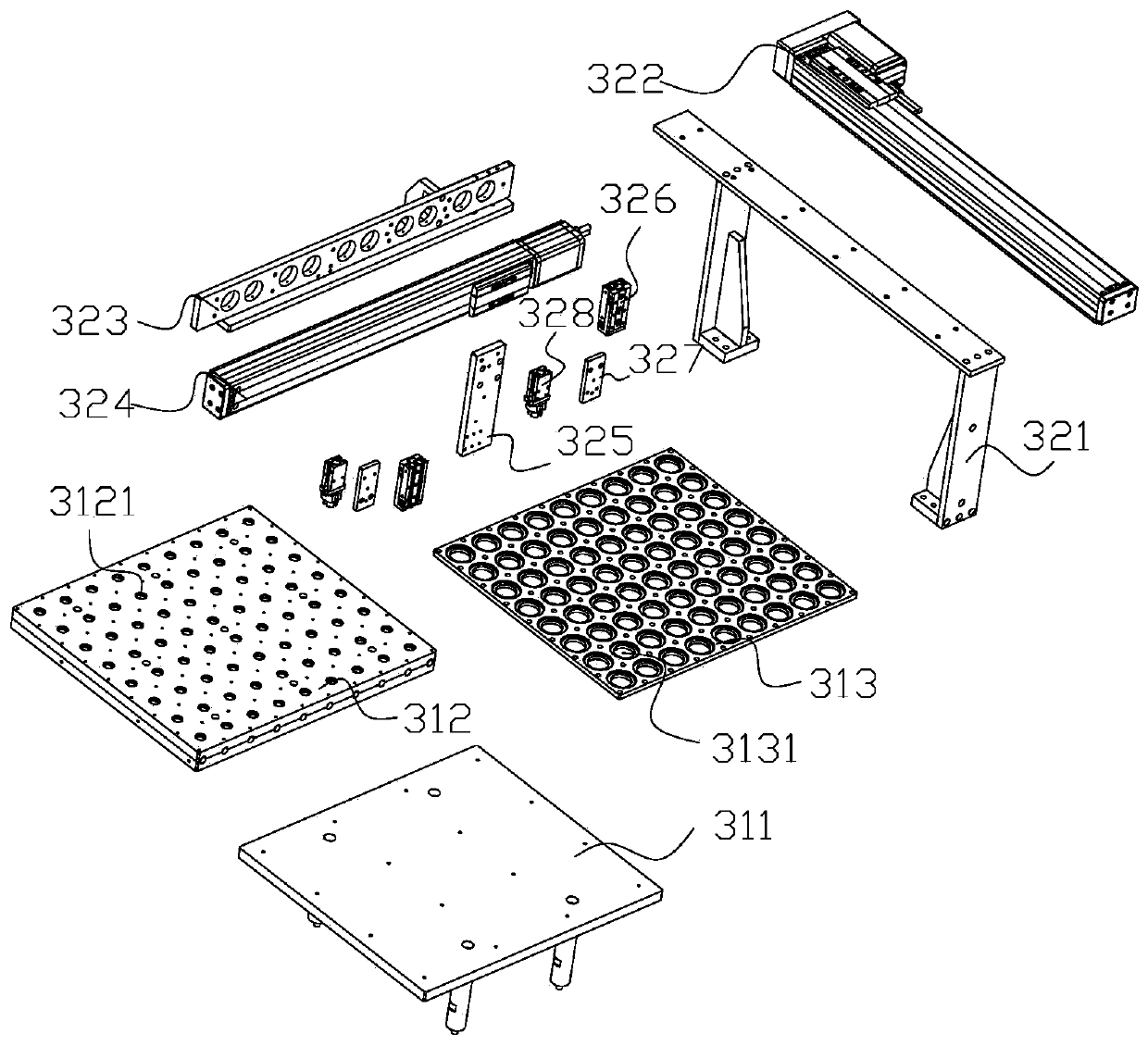
The invention relates to the field of micromotors, a micro motor housing and an end cover assembly method. The housing moving component in the housing feeding device can move a housing material belowthe housing grabbing component, the housing grabbing component grabs the housing material onto a heating device, a heating transportation part transports the housing material to a heating part for heating; a measuring grabbing component in an amplitude measuring device transports the housing material onto a measuring housing carrier for amplitude measurement through a probe; a pressing material transportation component in a pressing device transports the housing material onto a pressing component, an end cover feeding component is adopted for end cover transportation feeding, a pressing component is used for assembling, and a detection grabbing component is adopted for cooperation to transport a finished product onto the detection device for detection and blanking. The micro motor housingand the end cover assembly method can achieves the automatic feeding of the housing, automatic heating and drying of glue, automatic measurement of the axial amplitude, automatic feeding of the end cover, housing assembling and automatic detection of the overflowing action.

Description

technical field [0001] The invention relates to the field of micro motors. Background technique [0002] At present, in the assembly and production of micro motors, there has been a transition from manual assembly to automatic assembly of equipment. For example, a Chinese invention patent with the publication number CN104009594A (announcement date: 2014.08.27) discloses an automatic assembly machine for micro motors, including a frame and Stator and rotor feeding mechanism, rotor inlet mechanism, stator orientation and end cover assembly structure, riveting pressure detection mechanism installed on the frame, the stator and rotor feeding mechanism, rotor inlet mechanism, the The stator orientation and the end cover are combined into the structure, and the riveting pressure detection mechanism is sequentially connected to form. Compared with the traditional micro-motor, the micro-motor automatic assembly machine of the present invention has creative optimization in the assem...

Claims


Application Information

Patent Timeline
IPC IPC(8): H02K15/14
CPCH02K15/14
Inventor 王加皮孙洋徐叶苏
Owner 温岭市凯仕达电机有限公司
Learn More