Multi-channel thread rolling machine

A thread rolling machine and multi-channel technology, which is applied in the field of thread rolling machines, can solve problems such as low efficiency, and achieve the effect of improving production efficiency and equipment utilization

Inactive Publication Date: 2019-11-05
海盐永捷科技股份有限公司
View PDF5 Cites 2 Cited by
  • Summary
  • Abstract
  • Description
  • Claims
  • Application Information

AI Technical Summary

Problems solved by technology

[0003] At present, the thread rolling machine usually includes a flywheel, a moving plate, a fixed plate and a blank conveying channel. The blanks are sorted to the conveying channel through the vibrating plate, and the blanks are conveyed one by one between the moving plate and the fixed plate through the conveying channel. The flywheel and the moving plate A connecting rod is set between them, and through the continuous rotation of the flywheel, the moving plate reciprocates relative to the fixed plate. When the flywheel rotates once, it is a cycle. At present, only one blank can be thread-rolled in each cycle, and the efficiency is low. To improve production efficiency, it is usually necessary to set up multiple thread rolling machines

Method used


Image

  • Multi-channel thread rolling machine
  • Multi-channel thread rolling machine

Examples


Embodiment Construction

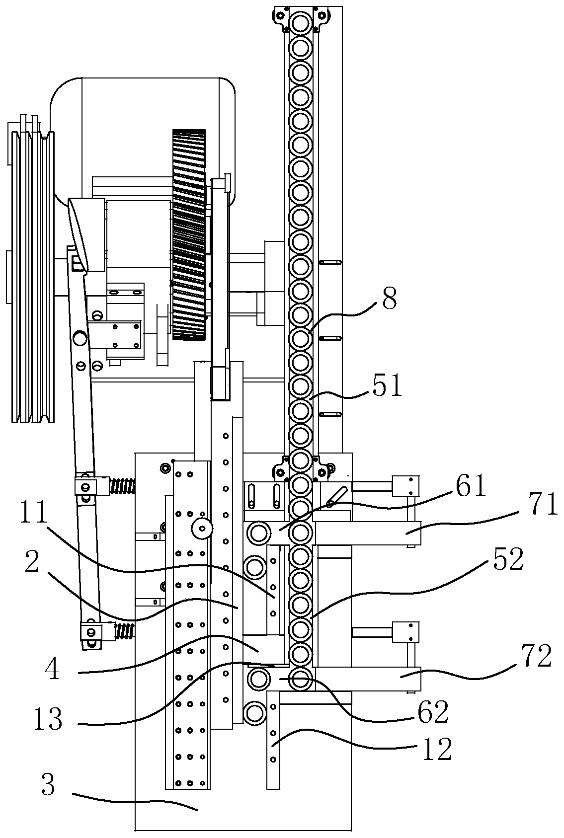
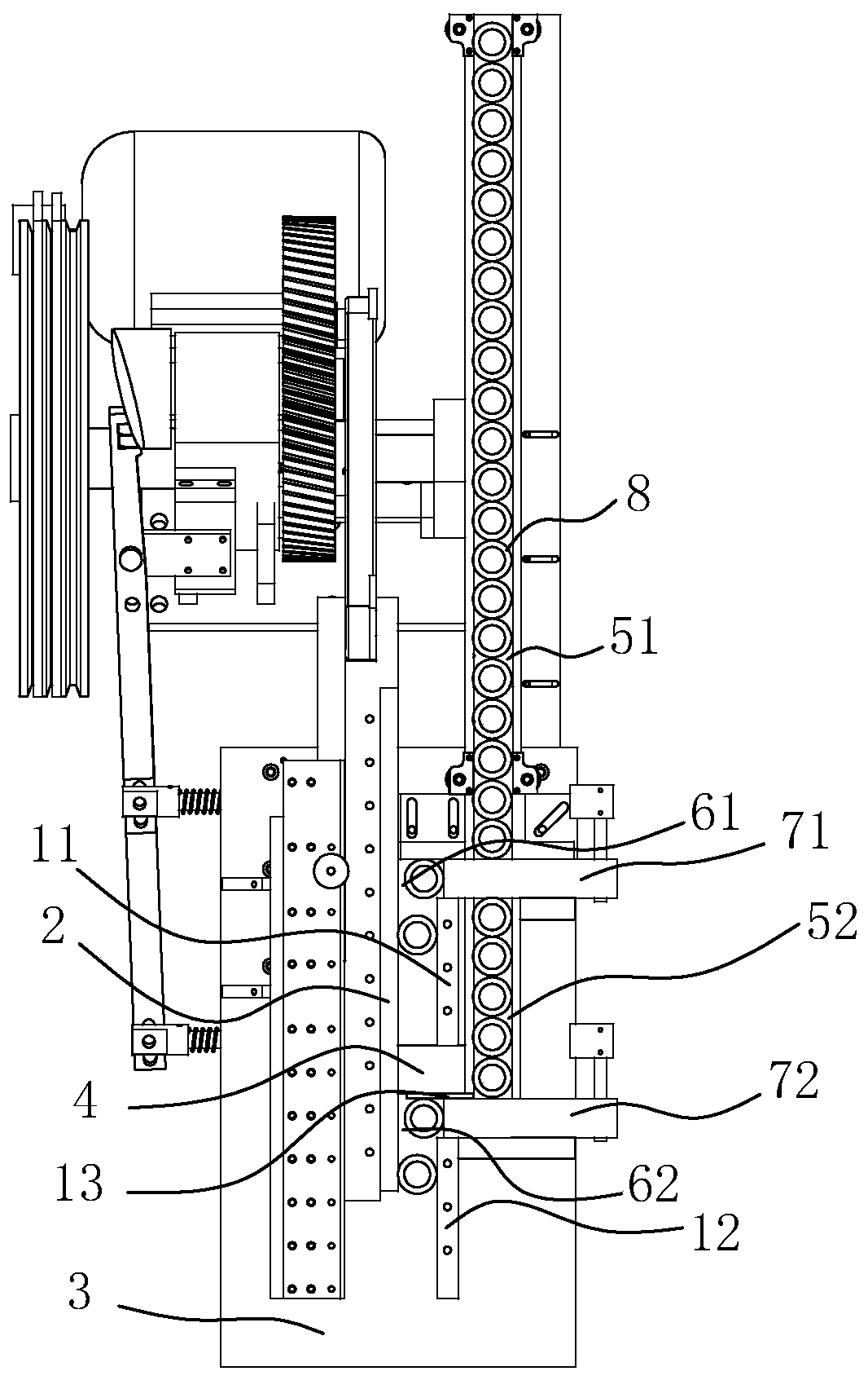
[0016] refer to figure 1 and figure 2 The embodiment of the multi-channel thread rolling machine of the present invention will be further described.

[0017] In the description of the present invention, it should be noted that for orientation words, such as the term "center", "horizontal (X)", "longitudinal (Y)", "vertical (Z)", "length", " Width", "Thickness", "Top", "Bottom", "Front", "Back", "Left", "Right", "Vertical", "Horizontal", "Top", "Bottom", "Inner ", "outside", "clockwise", "counterclockwise" and other indication orientations and positional relationships are based on the orientation or positional relationship shown in the drawings, and are only for the convenience of describing the present invention and simplifying the description, rather than indicating or implying the Means that a device or element must have a specific orientation, be constructed and operated in a specific orientation should not be construed as limiting the specific protection scope of the pr...


PUM


Abstract

The invention discloses a multi-channel thread rolling machine which comprises a flywheel, a movable plate, fixed plates and conveying passages. The fixed plates comprise the first fixed plate and thesecond fixed plate, a first thread rolling zone is formed between the first fixed plate and the movable plate, a second thread rolling zone is formed between the second fixed plate and the movable plate, a first discharging zone is reserved between an end point of the first thread rolling zone and a starting point of the second thread rolling zone, a first feeding passage is arranged at the starting point of the first thread rolling zone, a first pushing member doing reciprocated movement is arranged on the first feeding passage, a second feeding passage is arranged at the starting point of the second thread rolling zone, and a second pushing member doing reciprocated movement is arranged on the second feeding passage. When the flywheel rotates by a circle and the movable plate performs one periodic motion, two blanks can be subjected to thread rolling at the same time, the production efficiency is improved by one time, separable addition of one thread rolling machine is not needed, the occupied site is small, and cost is saved.

Description

technical field [0001] The invention belongs to the field of thread rolling machines, and more specifically relates to a multi-channel thread rolling machine. Background technique [0002] Thread rolling machine is an equipment specialized in the production of screws. Thread rolling machine, there are various specifications of thread rolling machines, such as automatic thread rolling machine, flat plate thread rolling machine, semi-automatic thread rolling machine, automatic thread rolling machine, high-speed thread rolling machine, etc. [0003] At present, the thread rolling machine usually includes a flywheel, a moving plate, a fixed plate and a blank conveying channel. The blanks are sorted to the conveying channel through the vibrating plate, and the blanks are conveyed one by one between the moving plate and the fixed plate through the conveying channel. The flywheel and the moving plate A connecting rod is set between them, and through the continuous rotation of the ...

Claims


Application Information

Patent Timeline
IPC IPC(8): B21H3/06B21H9/00
CPCB21H3/06B21H9/00
Inventor 沈华锋
Owner 海盐永捷科技股份有限公司
Why Eureka
Try Eureka