Three-dimensional adjustable high-pressure-bearing high dynamic water grouting system and testing method
A grouting system and adjustable technology, which is applied in the direction of measuring devices, instruments, suspensions and porous material analysis, etc., can solve the problems of small size of test devices, narrow application range, poor device adjustability, etc., to achieve timely water supply, Improved utilization and good adjustability
Active Publication Date: 2019-11-05
SHANDONG JIANZHU UNIV
View PDF10 Cites 0 Cited by
- Summary
- Abstract
- Description
- Claims
- Application Information
AI Technical Summary
Problems solved by technology
[0005] 1) The size of the test device is generally small and fixed, and the utilization rate of the test device is low
[0006] 2) It can only simulate single plate cracks or Monte Carlo cross cracks, and cannot simulate porous media such as pebbles, sand, etc.
[0007] 3) The amount of grout stored in the pressure-bearing cylinder is limited and the position of the grout surface in the cylinder cannot be observed, and the pressure-bearing cylinder lacks a pressure relief device, which is u
Method used
View moreImage
Smart ImageViewing Examples
Examples
 PUM
 Abstract
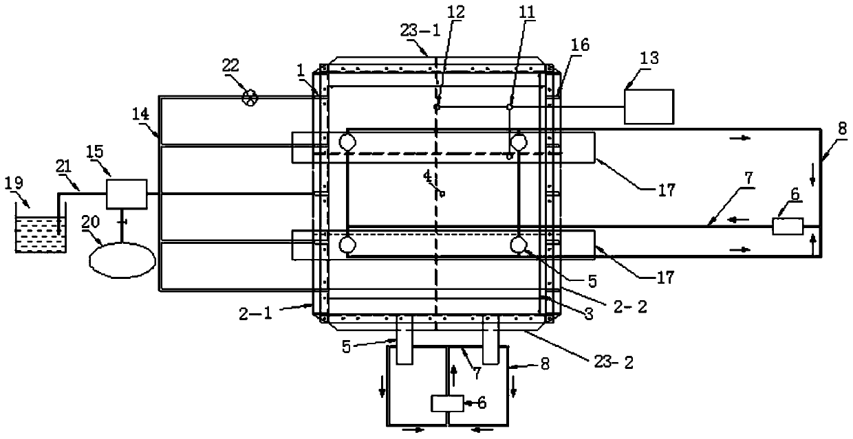
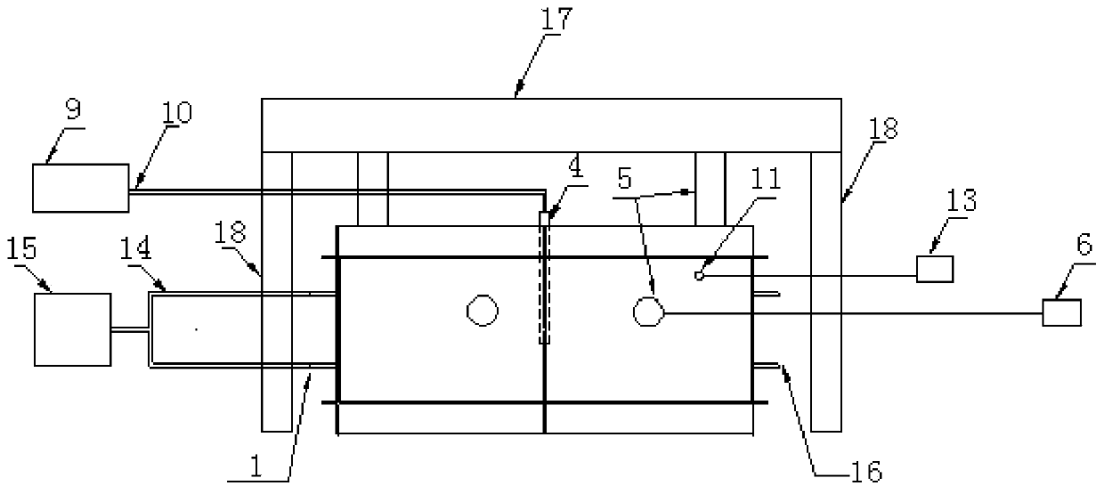
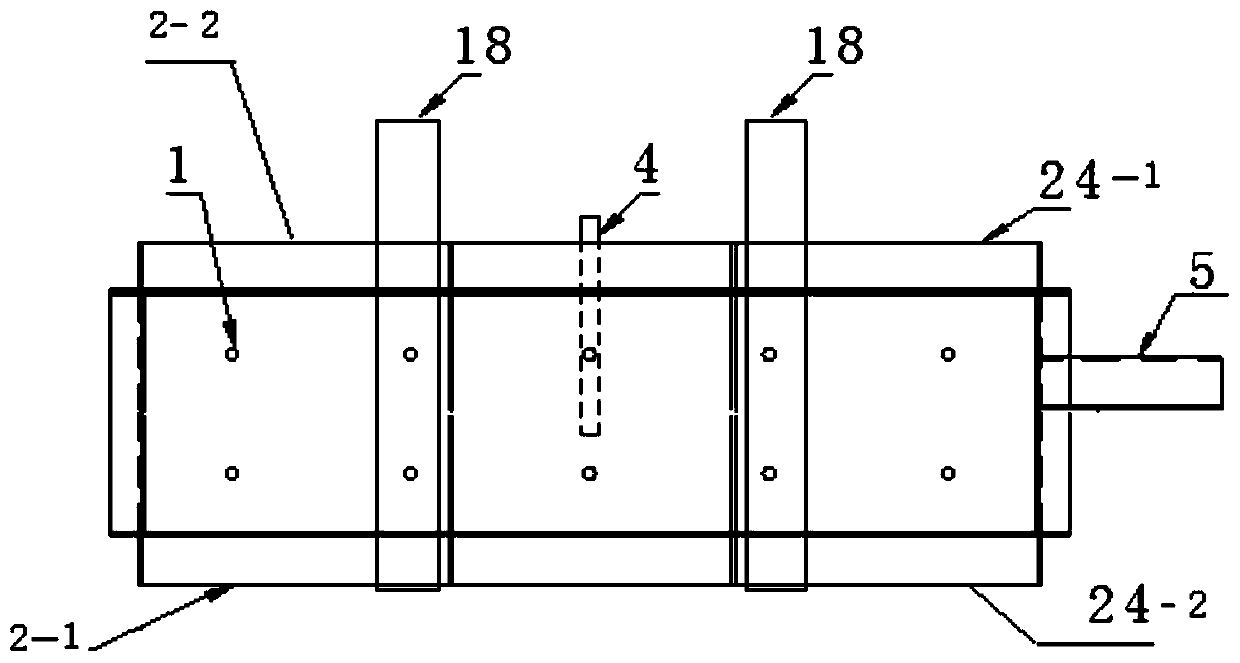
The invention provides a three-dimensional adjustable high-pressure-bearing high dynamic water grouting system and a testing method. The three-dimensional adjustable high-pressure-bearing high dynamicwater grouting system comprises a model cabin frame, a loading system, a grouting system, a dynamic water system and a monitoring system. The model cabin frame is composed of an upper plate, a lowerplate, a left plate, a right plate, a front plate and a rear plate; the upper plate and the lower plate are composed of a plurality of first basic modules, the left plate and the right plate are composed of a plurality of second basic modules, and the front plate and the rear plate are composed of a plurality of third basic modules; the model cabin frame is used for being filled with a geomaterial, and the size of the filling space is adjustable. The loading system is used for simulating the stress condition in a pressure-bearing state at a preset burial depth. The grouting system is used forcarrying out a grouting test on the geomaterial in the model cabin frame. The dynamic water system is used for injecting water into the geomaterial in the model cabin frame to simulate dynamic water with a preset pressure and a preset flow. The monitoring system is used for monitoring the stress condition of the geomaterial in the model cabin frame, the internal pore water pressure and the water flow information.
Description
technical field [0001] The disclosure belongs to the field of rock-soil model tests, and in particular relates to a three-dimensional adjustable high-pressure large-dynamic water grouting system and a test method. Background technique [0002] The statements in this section merely provide background information related to the present disclosure and do not necessarily constitute prior art. [0003] At present, scholars at home and abroad have developed a series of test devices for disaster prevention and control in deep underground engineering, which has promoted the development of rock-soil medium grouting theory to a certain extent, but there are also certain shortcomings. For example, the size of the test device is fixed, the dimension of the pressure applied is limited and the pressure is low, and the grouting test is mostly in a static water environment or the hydrodynamic pressure provided is low, which contradicts the actual background of many deep underground projects...
Claims
Login to View More Application Information
Patent Timeline
 IPC IPC(8): G01N13/04G01N15/08
CPCG01N13/04G01N15/082
Inventor 冯啸宋曙光孔祥辉于晓桦胡文军赵全满殷敬敬谢璨
Owner SHANDONG JIANZHU UNIV
Features
- R&D
- Intellectual Property
- Life Sciences
- Materials
- Tech Scout
- Unparalleled Data Quality
- Higher Quality Content
- 60% Fewer Hallucinations
Learn More Browse by: Latest US Patents, China's latest patents, Technical Efficacy Thesaurus, Application Domain, Technology Topic, Popular Technical Reports.
© 2025 PatSnap. All rights reserved.Legal|Privacy policy|Modern Slavery Act Transparency Statement|Sitemap|About US| Contact US: help@patsnap.com


