
Ventilation and rainproof power supply box

A box and power supply technology, applied in the cooling/ventilation of substations/switchgears, electrical components, substation/distribution device enclosures, etc. problems, to achieve a good working environment, improve service life, improve the effect of working performance

Active Publication Date: 2019-11-05
HEFEI TONGYONG POWER EQUIP
View PDF9 Cites 5 Cited by
  • Summary
  • Abstract
  • Description
  • Claims
  • Application Information

AI Technical Summary

Problems solved by technology

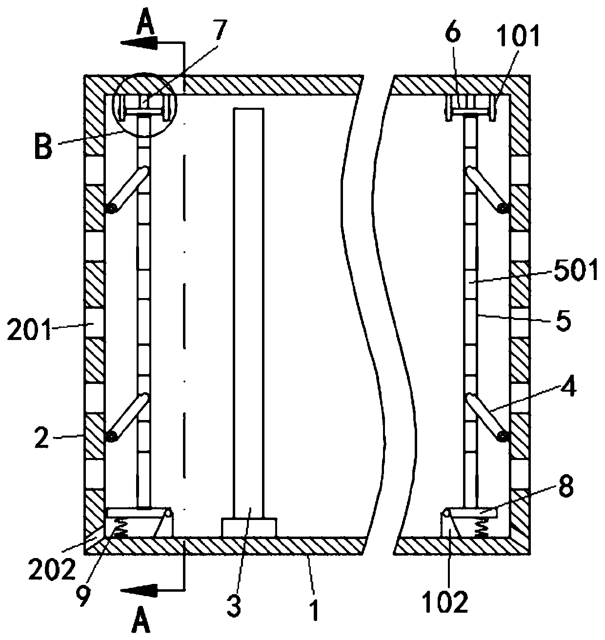
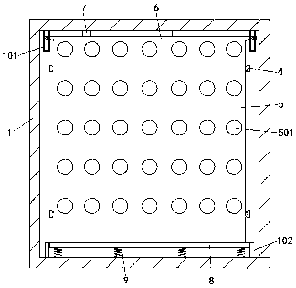
[0004] The purpose of the present invention is to provide a ventilated and rainproof power supply box. By comparing the temperature values ​​of the first temperature sensor and the second temperature sensor, the microprocessor controls the action of the telescopic rod, and finally makes the wind plate rise or fall, so as to ensure The first ventilation hole corresponds to or is staggered with the second ventilation hole, so that the first ventilation hole, the heat dissipation fan and the second ventilation hole form or do not form an air duct, thereby realizing the rainproof and heat dissipation capabilities of the wind plate to the side plate, It solves the problem that the working performance and service life of the existing power supply are reduced due to poor external installation environment, poor rainproof performance and poor ventilation capacity

Method used


Image

  • Ventilation and rainproof power supply box
  • Ventilation and rainproof power supply box
  • Ventilation and rainproof power supply box

Examples


Embodiment Construction

[0027] The following will clearly and completely describe the technical solutions in the embodiments of the present invention with reference to the accompanying drawings in the embodiments of the present invention. Obviously, the described embodiments are only some, not all, embodiments of the present invention. Based on the embodiments of the present invention, all other embodiments obtained by persons of ordinary skill in the art without creative efforts fall within the protection scope of the present invention.

[0028] In the description of the present invention, it should be understood that the terms "open", "down", "up", "middle", "near", etc. indicate orientation or positional relationship, and are only for the convenience of describing the present invention and simplifying the description, It is not intended to indicate or imply that the components or elements referred to must have a particular orientation, be constructed and operate in a particular orientation, and thu...


PUM


Abstract

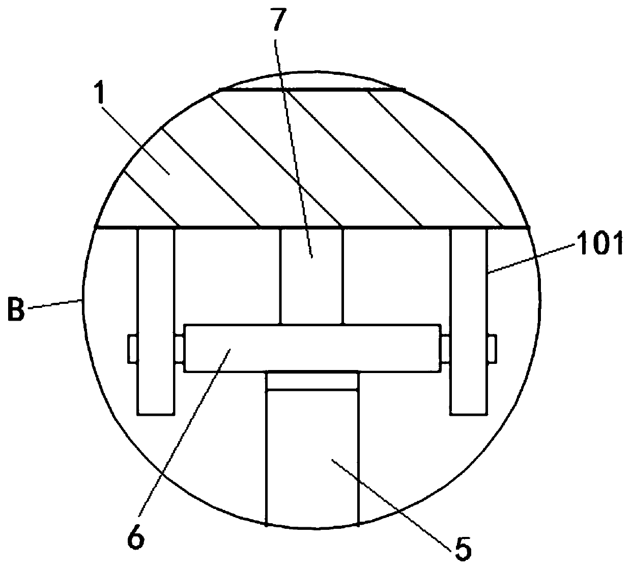
The invention discloses a ventilation and rainproof power supply box and relates to the technical field of power supplies. The ventilation and rainproof power supply box comprises a box body, the boxbody comprises opposite side plates, a plurality of first ventilation holes are set on the side plates. A heat dissipation fan is installed in the box body and is located between the two side plates.Inner side walls of the two side plates are hinged to fan plates through a plurality of hinge rods. The wind plates are uniformly provided with a plurality of second ventilation holes, and tops of thewind plates are in contact with the lower surfaces of pressing plates. A microprocessor is allowed to control the movement of the telescopic rods by comparing temperature values of a first temperature sensor and a second temperature sensor, finally the wind plates go up or down to ensure that the first ventilation holes are corresponding to or offset from the second ventilation holes, therefore,a wind channel is formed or not formed by the first ventilation holes, the heat dissipation fan and the second ventilation holes, the rainproof and heat dissipation ability of the wind plates to the side plates is achieved, a good working environment is provided for electronic components inside the box, and the service life and performance of the power supply are improved.

Description

technical field [0001] The invention belongs to the technical field of power supplies, in particular to a ventilation and rainproof power supply box. Background technique [0002] The power supply box provides external security for the electronic components inside; however, the installation environment and service life are different with the application of the power supply; when it is installed in an external exposure environment, rain may cause the power box to The components inside the body are short-circuited and damaged; but when using a fully enclosed shell, its ventilation performance is guaranteed; but when using a semi-closed shell, its ventilation and rain-proof performance is difficult to take into account; it cannot provide safety for people's normal use later. [0003] Therefore, a kind of ventilated and rainproof power supply box needs to be studied to improve the ventilation and rain-proof performance of the power supply box, and provide a good operating enviro...

Claims


Application Information

Patent Timeline
Patent Type & Authority Applications(China)
IPC IPC(8): H02B1/56H02B1/46H02B1/28
CPCH02B1/28H02B1/46H02B1/565
Inventor 岑磊岑玲池玉东王霞
Owner HEFEI TONGYONG POWER EQUIP
Learn More