Self-driving control device

A technology of automatic driving control and control device, which is applied in the direction of control device, automatic starting device, automatic steering control components, etc., can solve the problem of high computing load and achieve the effect of improving reliability

Active Publication Date: 2019-11-05
HITACHI ASTEMO LTD
View PDF12 Cites 0 Cited by
  • Summary
  • Abstract
  • Description
  • Claims
  • Application Information

AI Technical Summary

Problems solved by technology

[0004] On the other hand, the calculation load of the host control device is usually high

Method used


Image

  • Self-driving control device
  • Self-driving control device
  • Self-driving control device

Examples


Embodiment Construction

[0026] Next, an automatic driving control device according to an embodiment of the present invention will be described using the drawings. In this embodiment, an appropriate calculation result is output when outputting a result of calculation based on input signals from various sensors mounted on the control object to the electronic control unit.

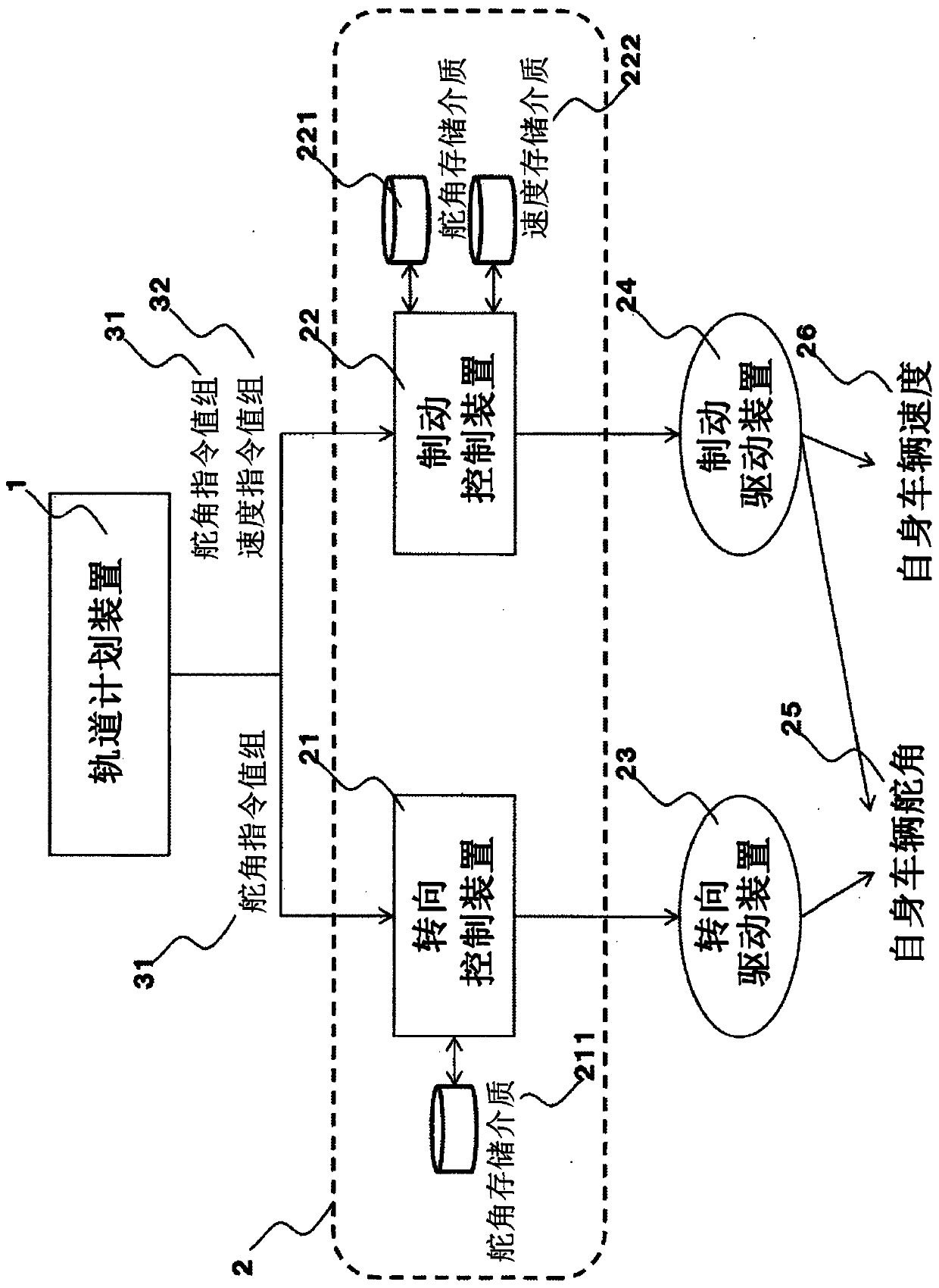
[0027] figure 1 The overall configuration of the automatic driving system in this embodiment is shown. This system includes a trajectory planning device 1 as a high-level control device, and the trajectory planning device 1 observes the self-vehicle state quantity input from an external information observation device such as a sensor not shown in the figure, and a self-vehicle state quantity observation device mounted on the self-vehicle. value as an input, and converts the trajectory of the own vehicle including the speed command value and rudder angle command value of the own vehicle into a rudder angle and a speed as output.

...


PUM


Abstract

The purpose of this invention is to improve the reliability of a self-driving system. A self-driving control device comprises a higher-order control device 1 which outputs a control target value for agroup of actuators on the basis of an action plan for a vehicle, and a lower-order control device 2 which controls the actuator group of the vehicle, on the basis of commands from the higher-order control device 1. The invention is constituted in such a manner that that the control target values for the vehicle which extend over a predetermined period of time and which are assigned by the higherorder control device 1 are held in the lower-order control device 2, and control is performed such that if the higher-order control device 1 does not satisfy a desired function, the lower-order control device 2 is controlled on the basis of the control target value which it holds, and by determining and correcting for any difference between the actual operation value of the vehicle and the controltarget value, the action plan for the vehicle is followed.

Description

technical field [0001] The invention relates to an automatic driving control device. Background technique [0002] In order to realize a highly automated driving system, for example, the higher-level control device (electronic control device) that controls the automatic driving requires a certain period of time before the operation is returned to the driver even if the device itself that controls the automatic driving fails. Continue to act within. [0003] In order to realize the continuation of the operation for a certain period of time, the multiple use of the system and the redundancy of the operation monitoring are considered. [0004] On the other hand, the calculation load of the host control device is usually high. [0005] To address such a problem, Patent Document 1 proposes a method in which a control command value is stored in advance in an upper control device (electronic control device), thereby continuing to drive devices (lower-level controllers) for a plur...

Claims


Application Information

Patent Timeline
Patent Type & Authority Applications(China)
IPC IPC(8): B60W50/029B60T7/12B60W10/18B60W10/184B60W10/20B62D6/00G05D1/02B62D101/00B62D113/00B62D137/00
CPCB60W10/18B60W10/20B60W50/029B60W60/0015B60W2520/10B60W2540/18B60W2720/10B60W2710/207G05D2201/0213G05D1/0055B60W50/00G05D1/0088B60W30/18B60W2710/20B60W2710/18
Inventor 堀口辰也广津铁平坂本英之稻田遼一
Owner HITACHI ASTEMO LTD
Why Eureka
Try Eureka