Swing type stepless rack locking device

A technology for locking devices and racks, which is applied in the field of swing-type stepless rack locking devices, and can solve problems such as damage to gears on the locking end face of fixed-length baffles, inability to achieve reliable locking, and inability to achieve stepless locking. , to achieve the effect of no need for manual intervention, simple structure, and good stress

Pending Publication Date: 2019-11-08
CHINA NAT HEAVY MACHINERY RES INSTCO
View PDF0 Cites 1 Cited by
  • Summary
  • Abstract
  • Description
  • Claims
  • Application Information

AI Technical Summary

Problems solved by technology

[0002] At present, in the steel pipe gang sawing machine equipment at home and abroad, the baffles used to measure the length of a row of steel pipes are all driven by rack and pinion. At present, there are two main locking methods: one is to use multiple sets of oil cylinders to press the guide rail surface. , the locking is realized by establishing a strong frictional force with the guide rail surface; the other is to lock the rack and the gear by locking the rotating shaft of the drive gear through the end gear. This locking method requires the meshing of the end teeth. Stepless locking is therefore not possible
However, in the process of sizing, the rows of steel pipes hit the sizing baffle at high speed and stop the sizing, so the impact on the sizing baffle is very serious. The above locking methods cannot achieve reliable locking, and the sizing block appears. The problem that the plate is knocked moving and the locking face gear is often damaged

Method used


Image

  • Swing type stepless rack locking device
  • Swing type stepless rack locking device

Examples


Embodiment Construction

[0013] Below in conjunction with accompanying drawing, structural principle and working principle of the present invention are further described:

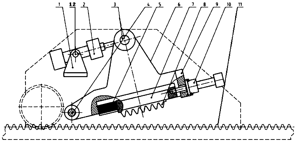
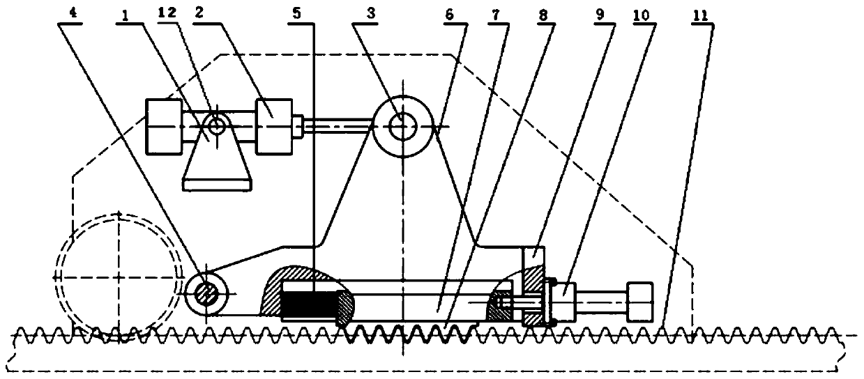
[0014] see figure 1 , figure 2 A swing-type stepless rack locking device is composed of two parts, a moving part and a fixed part, wherein the moving part includes an oil cylinder base 1, and the oil cylinder base 1 is connected to the middle section of the swing oil cylinder 2 through a hinge shaft 12, and the swing oil cylinder 2 The piston end of the swing arm 6 is connected to the top end of the swing arm 6 through the first pin shaft 3, one end of the bottom of the swing arm 6 is hinged with the second pin shaft 4, and the other end of the bottom of the swing arm 6 is connected with a stopper through an oil cylinder mounting seat 9. Oil cylinder 10; the bottom of the swing arm 6 is provided with a slideway 7, one end of the spring 5 is connected to the end of the slideway 7 close to the second pin shaft 4, and the other end ...


PUM


Abstract

The invention provides a swing type stepless rack locking device which comprises an oil cylinder base. The oil cylinder base is connected with a swing oil cylinder through a hinge shaft. The piston end of the swing oil cylinder is connected with the top end of a swing arm through a first pin shaft. One end of the bottom of the swing arm is hinged to a second pin shaft. The other end of the bottomof the swing arm is connected with a locking oil cylinder through an oil cylinder installing base. A slideway is arranged on the bottom of the swing arm. One end of a spring is connected to one end, close to the second pin shaft, of the slideway. A first rack is arranged in the slideway and located at the other end of the spring. A second rack is arranged below the first rack. According to the device, the oil cylinder drives the swing arm to swing, the first rack slides in the slideway linearly and is engaged with the second rack, and a gear and rack transmission mechanism can be locked reliably at any position, and does not shift under the circumstance of bearing large impact load. The locking device has the advantages that use is easy, stepless locking is achieved, locking is reliable, and manual intervention is not needed.

Description

technical field [0001] The invention relates to a locking device, in particular to a swing type stepless rack locking device. Background technique [0002] At present, in the steel pipe gang sawing machine equipment at home and abroad, the baffles used to measure the length of a row of steel pipes are all driven by rack and pinion. At present, there are two main locking methods: one is to use multiple sets of oil cylinders to press the guide rail surface. , the locking is realized by establishing a strong frictional force with the guide rail surface; the other is to lock the rack and the gear by locking the rotating shaft of the drive gear through the end gear. This locking method requires the meshing of the end teeth. Therefore stepless locking cannot be achieved. However, in the process of sizing, the rows of steel pipes hit the sizing baffle at high speed and stop the sizing, so the impact on the sizing baffle is very serious. The above locking methods cannot achieve rel...

Claims


Application Information

Patent Timeline
Patent Type & Authority Applications(China)
IPC IPC(8): B25B27/02
CPCB25B27/026
Inventor 雷超贾楠解吉辉刘录锋孙丽丽杨晓东
Owner CHINA NAT HEAVY MACHINERY RES INSTCO
Why Eureka
Try Eureka