
Bonding equipment and lens bonding method

A technology for laminating equipment and lenses, applied in instruments, polarizing elements, optics, etc., can solve problems such as inability to AA alignment of workpieces, to ensure adhesion and reliability, ensure alignment, and meet the needs of optical path design. Effect

Active Publication Date: 2021-08-24
INTERFACE TECH CHENGDU CO LTD +2
View PDF10 Cites 0 Cited by
  • Summary
  • Abstract
  • Description
  • Claims
  • Application Information

AI Technical Summary

Problems solved by technology

[0003] Based on this, it is necessary to provide a laminating equipment and a laminating method for lenses to solve the problem that the traditional STH equipment cannot perform AA alignment on the workpiece.

Method used


Image

  • Bonding equipment and lens bonding method
  • Bonding equipment and lens bonding method
  • Bonding equipment and lens bonding method

Examples


Embodiment Construction

[0027] In order to facilitate the understanding of the present invention, the present invention will be described more fully below with reference to the associated drawings. Preferred embodiments of the invention are shown in the accompanying drawings. However, the present invention can be embodied in many different forms and is not limited to the embodiments described herein. On the contrary, the purpose of providing these embodiments is to make the disclosure of the present invention more thorough and comprehensive.

[0028] It should be noted that when an element is referred to as being “fixed” to another element, it can be directly on the other element or there can also be an intervening element. When an element is referred to as being "connected to" another element, it can be directly connected to the other element or intervening elements may also be present. The terms "inner", "outer", "left", "right" and similar expressions are used herein for the purpose of descripti...


PUM

PropertyMeasurementUnit
angleaaaaaaaaaa
angleaaaaaaaaaa

Abstract

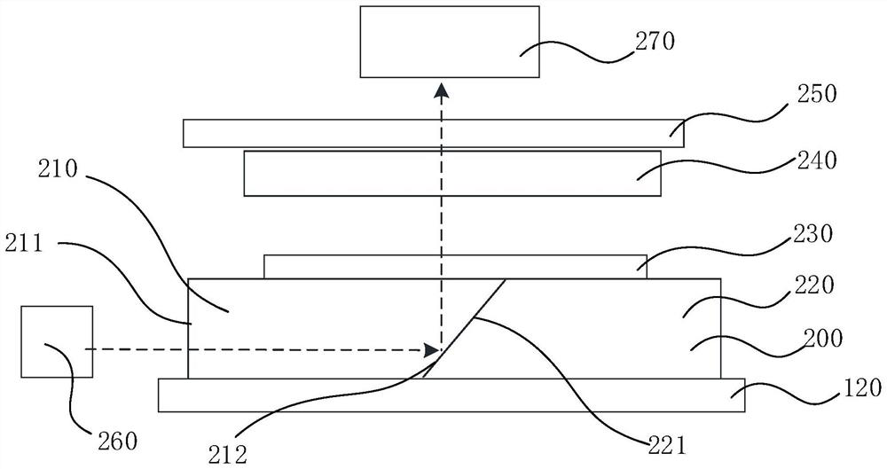
The present invention relates to a laminating equipment and a laminating method of lenses, wherein the laminating equipment includes: a light source for emitting incident light beams; The index of refraction is smaller than that of the second jig. The first jig has an incident surface and a first reflective surface oppositely arranged. The incident surface is used to receive the incident light beam. The second jig has a second reflective surface. The first reflective surface and the first reflective surface The two reflective surfaces are in contact with each other and are used to reflect the incident beam, and the incident beam is reflected to form a reflected beam; the workbench is used to place at least two workpieces, and the reflected beam passes through the workpiece to form an outgoing beam; the detector is used to detect the outgoing beam The intensity of the beam, and then judge whether the workpiece is aligned. The bonding equipment of the present invention has the AA alignment function, and the bonding method of the lens of the present invention not only enables the APF film to be bonded to the lens through UV OCA glue, but also ensures the alignment between the APF film and the QWP film, Meet the needs of optical path design.

Description

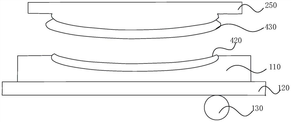
technical field [0001] The invention relates to the field of optical lens processing, in particular to a bonding equipment and a bonding method of lenses. Background technique [0002] In traditional soft-to-hard (STH, Soft To Hard) lamination equipment, such as figure 1 As shown, the workpiece, such as a QWP film (quarter wave plate) 420, is arranged on a workbench, and the workbench includes a rubber fixture 110, a mesh plate 120 and a roller 130, and the rubber fixture 110 and the mesh plate 120 are below the workpiece And roller 130 and other opaque parts, the active alignment (Active Alignment, referred to as AA alignment) light source cannot align the workpiece through these opaque parts, so that the traditional STH equipment does not have the AA alignment function. Contents of the invention [0003] Based on this, it is necessary to provide a laminating equipment and a laminating method for lenses to solve the problem that the traditional STH equipment cannot perfo...

Claims


Application Information

Patent Timeline
Patent Type & Authority Patents(China)
IPC IPC(8): B29C65/48B29C65/78G02B5/30
CPCB29C65/4845B29C65/7805B29C66/472G02B5/3083
Inventor 万宝辉
Owner INTERFACE TECH CHENGDU CO LTD
Learn More