Vacuum packaging structure, packaging method thereof, and vacuum packaging device

A vacuum packaging and vacuum cavity technology, applied in electrical components, electrical solid devices, circuits, etc., can solve the problems of large size, uneven temperature distribution of chip substrates, affecting performance, etc., to achieve good temperature uniformity and ensure performance. , the effect of reducing the size

Active Publication Date: 2017-06-13
ZHEJIANG DALI TECH +1
View PDF3 Cites 19 Cited by
  • Summary
  • Abstract
  • Description
  • Claims
  • Application Information

AI Technical Summary

Problems solved by technology

This structure has a large size in the height direction, and the infrared detector chip is in a suspended state, which will lead to uneven temperature distribution on the chip substrate during the working process and affect performance
[0020] The performance of the above-mentioned infrared detector packaging structure without an exhaust pipe needs to be further improved

Method used


Image

  • Vacuum packaging structure, packaging method thereof, and vacuum packaging device
  • Vacuum packaging structure, packaging method thereof, and vacuum packaging device
  • Vacuum packaging structure, packaging method thereof, and vacuum packaging device

Examples


Embodiment Construction

[0042] The specific implementation of the vacuum packaging structure, packaging method, and vacuum packaging device provided by the present invention will be described in detail below with reference to the accompanying drawings.

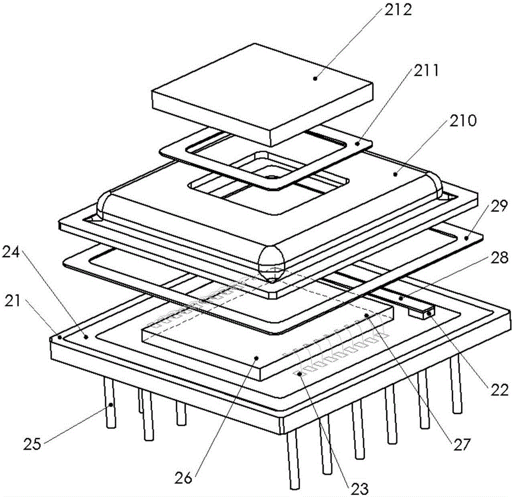
[0043] Please refer to figure 2 , the vacuum packaging structure is a vacuum packaging structure of an infrared detector chip, specifically comprising: a base 21 , a cap 210 , an infrared filter 212 , an infrared detector chip 26 and a getter layer 28 .

[0044] The material of the base 21 is ceramic, and the bottom of the base 21 may also be welded with metal pins 25 as electrical connection pins. The welding area 24 on the surface of the base 21 is plated with gold to form a firm weld with the cap 210 , and the thickness of the gold plating is greater than or equal to 0.8 microns.

[0045] The material of the cap 210 is Kovar. In other specific embodiments of the present invention, the material of the cap 210 can also be other metal materials wit...


PUM


Abstract

A vacuum packaging structure, a packaging method thereof, and a vacuum packaging device are provided. The vacuum packaging structure comprises: a base; a cover cap having an opening at the top, wherein the opening is covered with an infrared filter, and the cover cap, the infrared filter and the base form a vacuum chamber; an infrared detector chip positioned in the vacuum chamber and adhering to the surface of the base; and a getter layer located within the vacuum chamber and having both ends welded to the base surface. The vacuum packaging structure requires no exhaust pipe, simplifies components, and significantly reduces the volume of an infrared detector. Moreover, the infrared detector chip completely fits with the base, and a chip base material has good temperature uniformity and effectively guarantees detector performance.

Description

technical field [0001] The invention relates to the technical field of packaging, in particular to a vacuum packaging structure, a packaging method, and a vacuum packaging device. Background technique [0002] With the development of infrared thermal imaging technology, there are more and more application scenarios of infrared thermal imaging technology, including small devices such as hand-held and portable, which put forward strict requirements on the size and power consumption of infrared detectors. Uncooled infrared focal plane detector chips need to work in a vacuum environment for better performance. At present, uncooled focal plane infrared detectors are generally packaged in metal tubes with exhaust pipes. [0003] Please refer to figure 1 , is an exploded view of the structure of an infrared detector in the prior art. The infrared detector is packaged in a metal shell with an exhaust pipe, which has a large volume, many components, and a complicated process flow. ...

Claims


Application Information

Patent Timeline
Patent Type & Authority Applications(China)
IPC IPC(8): H01L23/26H01L23/10H01L21/67
CPCH01L23/26H01L21/67126H01L23/10
Inventor 钱剑潘峰姜利军
Owner ZHEJIANG DALI TECH
Why Eureka
Try Eureka