Piston assembly for linear compressor

A linear compressor and piston assembly technology, applied in the field of compressors, can solve problems such as spring failure, increased clearance volume, and fracture of the joint of the suction valve plate, and achieve a good sealing effect

Active Publication Date: 2019-11-08
CHENGDU ZHENGSHENG ENERGY TECH DEV CO LTD
View PDF13 Cites 2 Cited by
  • Summary
  • Abstract
  • Description
  • Claims
  • Application Information

AI Technical Summary

Problems solved by technology

[0004] The object of the present invention is a piston assembly for a linear compressor. The technical problem to be solved is to fix the suction valve plate on the outer end surface of the piston by screw connection, which brings about the problem of increasing the clearance volume, or the suction valve plate is fixed by welding. It is fixed on the outer end surface of the welding column, and the welding column is fixed by a spring. Due to the existence of welding deformation, after a long time of work, the connection of the suction valve plate is broken, or due to the welding process, the end surface of the suction valve plate and the outer end surface of the piston Not parallel, after the spring works for a long time, the spring will fail, resulting in the reduction of the displacement of the compressor and the long-term working efficiency

Method used


Image

  • Piston assembly for linear compressor
  • Piston assembly for linear compressor
  • Piston assembly for linear compressor

Examples


Embodiment 1

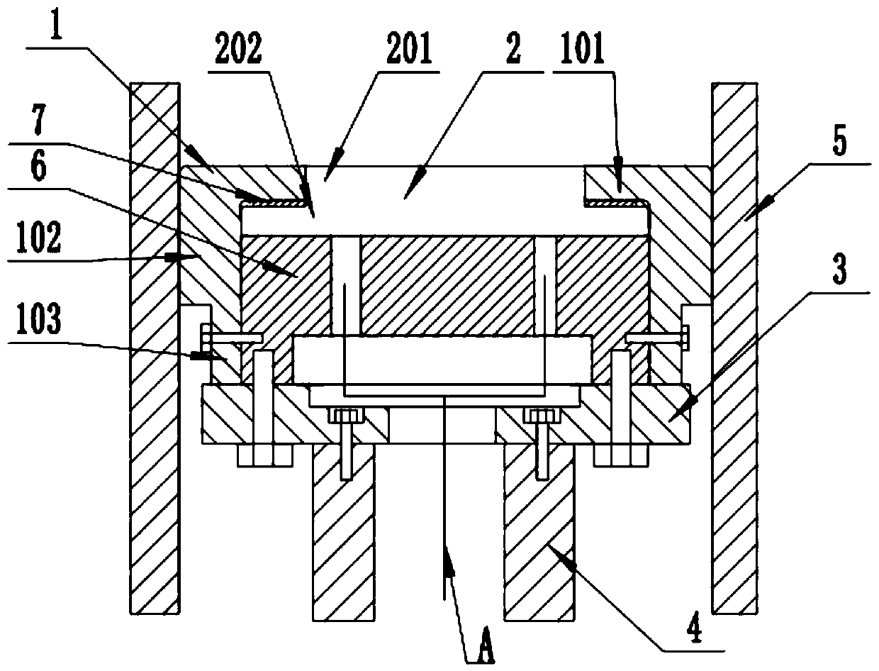
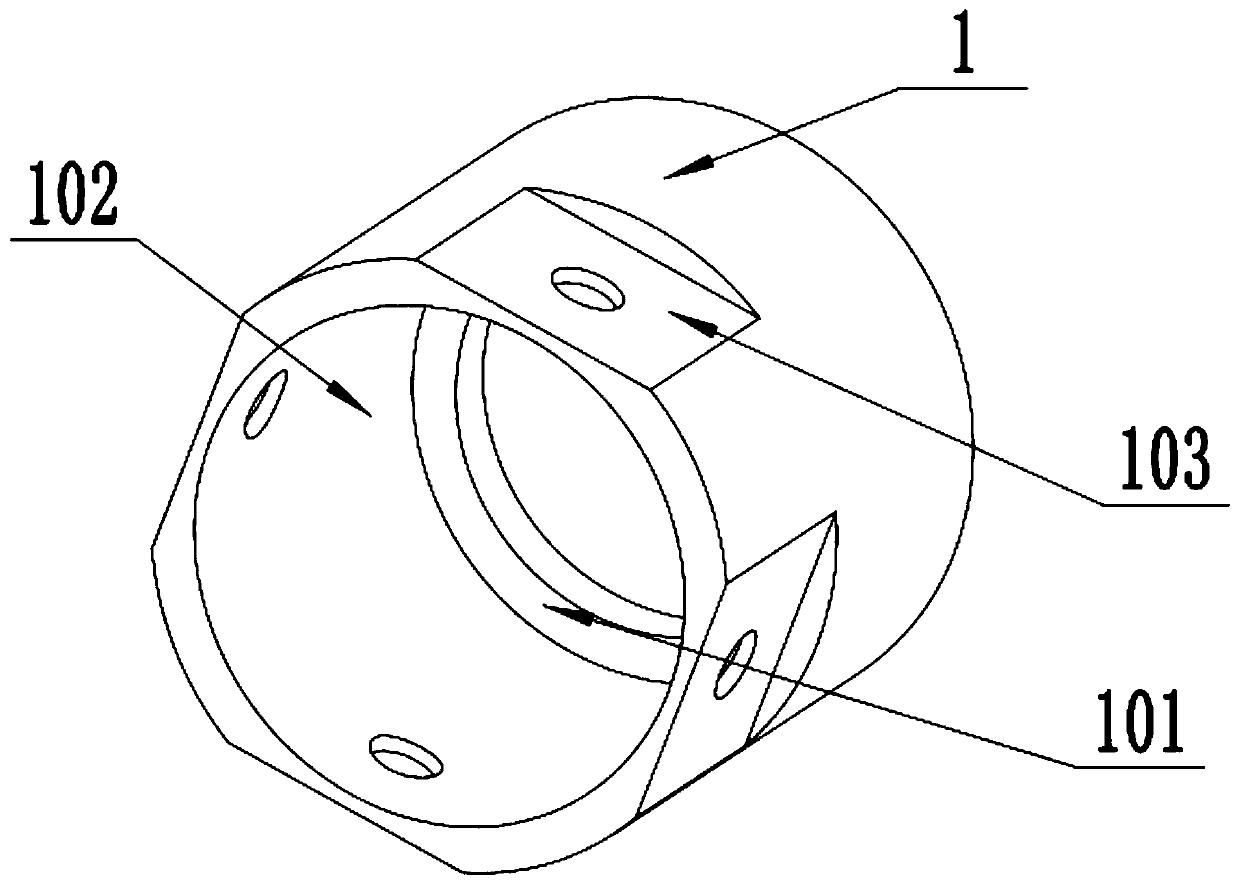
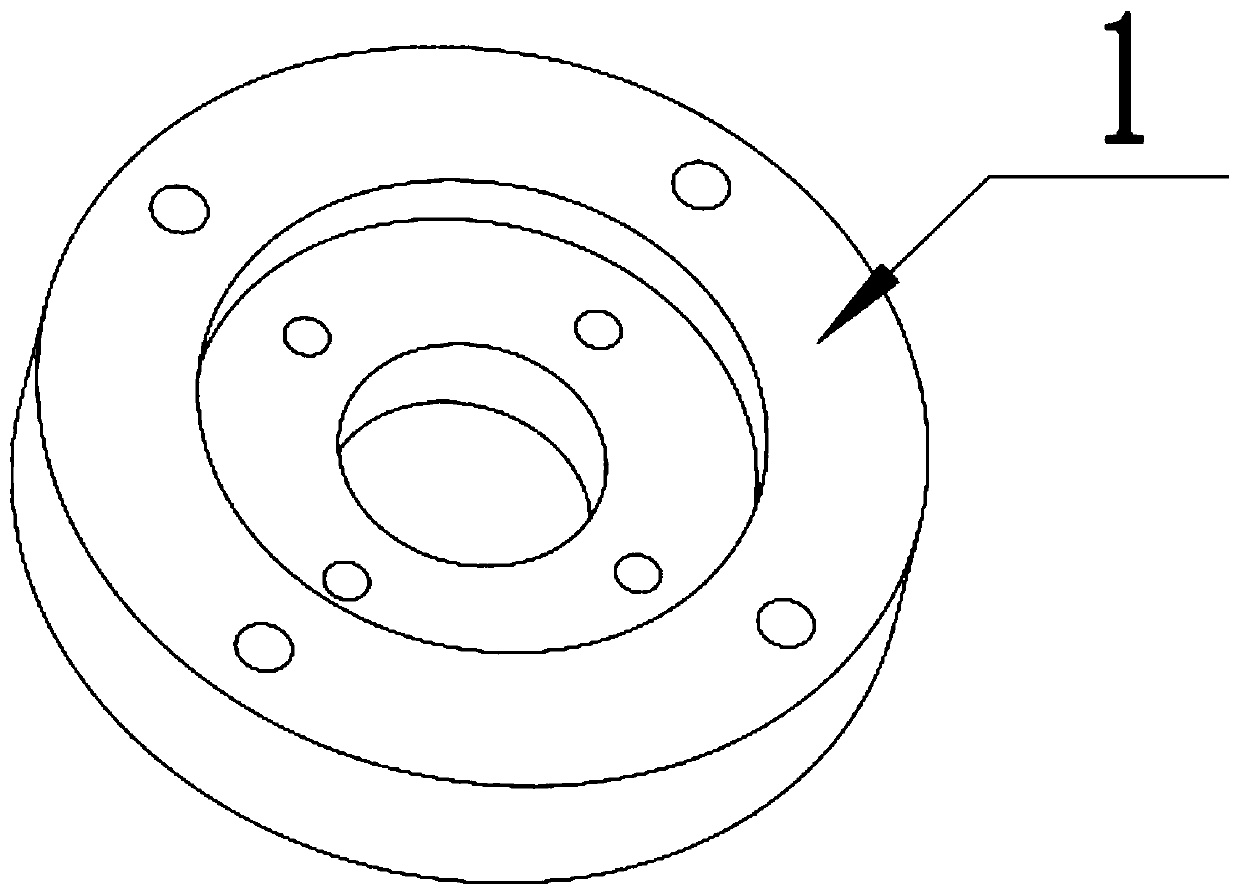
[0023] Such as Figure 1~4 As shown, a piston assembly for a linear compressor includes a suction valve plate 2, a connecting pipe 4, a piston cover 1, a connecting plate 3, and an intermediate block 6. The piston cover 1 is a hollow cylindrical structure, and one end of the piston cover 1 A flange 101 is arranged radially inwardly at the end of the piston cover 1. There are 4 evenly distributed planes 103 for setting threaded through holes on the outer wall of the piston cover 1. There is a threaded through hole on each plane. The suction valve plate 2 The shape is "convex", the part of the suction valve plate 2 with a small diameter is the first cylinder 201, the part with a large diameter of the suction valve plate 2 is the second cylinder 202, the suction valve plate 2 is arranged in the piston cover 1, and the suction The first cylinder 201 of the gas valve plate 2 is embedded in the flange 101 of the piston cover 1, and the end face of the first cylinder 201 of the sucti...

Embodiment 2

[0026] Such as Figure 1~4 As shown, this embodiment is further limited on the basis of Embodiment 1, the shape of the middle block 6 is cylindrical, one end of the middle block 6 is provided with a circular groove, and the other end of the middle block 6 is provided with 6 uniform Distributed through holes, and the through holes communicate with the groove at one end of the middle block 6, and the outer wall of the middle block 6 is provided with four evenly distributed internal thread holes, the internal thread holes are close to the end of the groove, and the internal thread The hole axis is collinear with the threaded through-hole axis on plane 103 . The depth of the groove is 10-20mm, and if the depth is less than 10mm, it is not conducive to the circulation of refrigerant gas. If the depth is greater than 20mm, the size of the middle block is too large, which is of no benefit to the entire piston assembly and may reduce the stroke . Further, a protrusion is provided on...

Embodiment 3

[0029] Such as Figure 1~4 , this embodiment is further limited on the basis of Embodiment 1, the connecting plate 3 and the connecting pipe 4 are threaded, the connecting plate 3 and the middle block 6 are threaded, and the threaded connections in this embodiment are all Bolts are used for connection, and spring washers are used in conjunction with the bolts. In addition, there is an annular washer at the connection between the connecting plate 3 and the middle block 6 to prevent refrigerant leakage. The shape of the connecting plate 3 is a circular plate, the center of the connecting plate 3 is provided with a stepped through hole, the peripheral edge of the connecting plate 3 is provided with 4 evenly distributed threaded through holes, and the step of the connecting plate 3 is provided with 4 evenly distributed threaded through holes. threaded through holes.

[0030] Furthermore, the suction valve plate 2 adopts a combination of a cylinder at the top and a truncated cone ...


PUM


Abstract

The invention discloses a piston assembly for a linear compressor. The piston assembly comprises an air suction valve block, connecting pipes, a piston cover, a connecting plate and a middle block, wherein the piston cover is of a hollow cylindrical structure; the air suction valve block is arranged in the piston cover; the middle block is arranged inside the [piston cover; in addition, one end ofthe middle block is closely fitted with the end face of a second cylinder of the air suction valve block; the other end of the middle block is connected with one end of the connecting plate; the other end of the connecting plate is connected with one end of each connecting pipe; the connecting plate, the connecting pipes and the middle block are all internally provided with channels for gases tocirculate; the channels are communicated after the connecting plate, the connecting pipes and the middle block are connected; and the channel of the middle block is communicated with the opening and closing parts of the air suction valve block. As the air suction valve block is arranged in the piston cover, a first cylinder of the air suction valve block is embedded into a flange of the piston cover; and in addition, the end face of the first cylinder of the air suction valve block is coplanar with the flange end face of the piston cover, so that the problems of clearance volume and the like are avoided.

Description

technical field [0001] The invention relates to the field of compressors, in particular to a piston assembly for a linear compressor. Background technique [0002] In refrigeration equipment such as refrigerators and freezers, linear compressors are often used. The linear compressor sucks the refrigerant gas into the cylinder, and uses the driving force of the linear motor to drive the piston to reciprocate linearly in the cylinder, thereby compressing the refrigerant gas. Finally, the refrigerant in the compressed state is discharged to the condenser. The piston of the linear compressor needs to be provided with an intake channel, and the suction valve is installed on the end surface of the piston. The traditional method is to fix the suction valve plate on the end face of the piston by screws, the screws protrude from the suction valve plate, and the exhaust valve plate corresponding to the screw should have a screw relief hole, but the existence of the relief hole increas...

Claims


Application Information

Patent Timeline
Patent Type & Authority Applications(China)
IPC IPC(8): F04B39/00F04B39/10
CPCF04B39/0016F04B39/10
Inventor 邓燕龙刘锦渝王开蓉
Owner CHENGDU ZHENGSHENG ENERGY TECH DEV CO LTD
Why Eureka
Try Eureka