Supercharge Your Innovation With Domain-Expert AI Agents!

Penetrating laser thickness gauge

A laser thickness measurement and penetrating technology, applied in the field of optical measurement, can solve the problems of large data difference, high production cost and low production efficiency

Pending Publication Date: 2019-11-08
宾努克斯科技(佛山)有限公司
View PDF0 Cites 2 Cited by
  • Summary
  • Abstract
  • Description
  • Claims
  • Application Information

AI Technical Summary

Problems solved by technology

However, mainly affected by factors such as the use of measuring tools, the uniformity of force, and the measurement position, the data obtained by different people often differ greatly, resulting in large errors. At the same time, manual measurement is time-consuming and labor-intensive, with low production efficiency and high production costs.

Method used


Image

  • Penetrating laser thickness gauge
  • Penetrating laser thickness gauge

Examples


Embodiment Construction

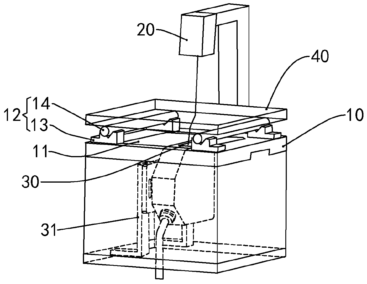
[0017] Such as figure 1 As shown, the penetrating laser thickness gauge of this embodiment includes a workbench 10 , a laser emitting device 20 and a CCD detection device 30 .

[0018] The workbench 10 is used for placing the transparent DUT 40 . Specifically in this embodiment, the workbench 10 is set horizontally, the workbench 10 is provided with a notch 11 and supports 12 arranged around the notch 11, the number of the supports 12 is two, and the two supports 12 are symmetrically arranged on Notch 11 both sides. The support 12 includes a bracket 13 and a roller 14 arranged on the bracket 13, the bracket 13 is arranged at both ends of the roller 14, the bracket 13 is fixed on the workbench 11, and the transparent DUT 40 is placed on the roller 14 on. The supporting member 12 is used to support the transparent DUT 40 , and the setting of the roller 14 helps to avoid scratching the transparent DUT 40 when the transparent DUT 40 moves.

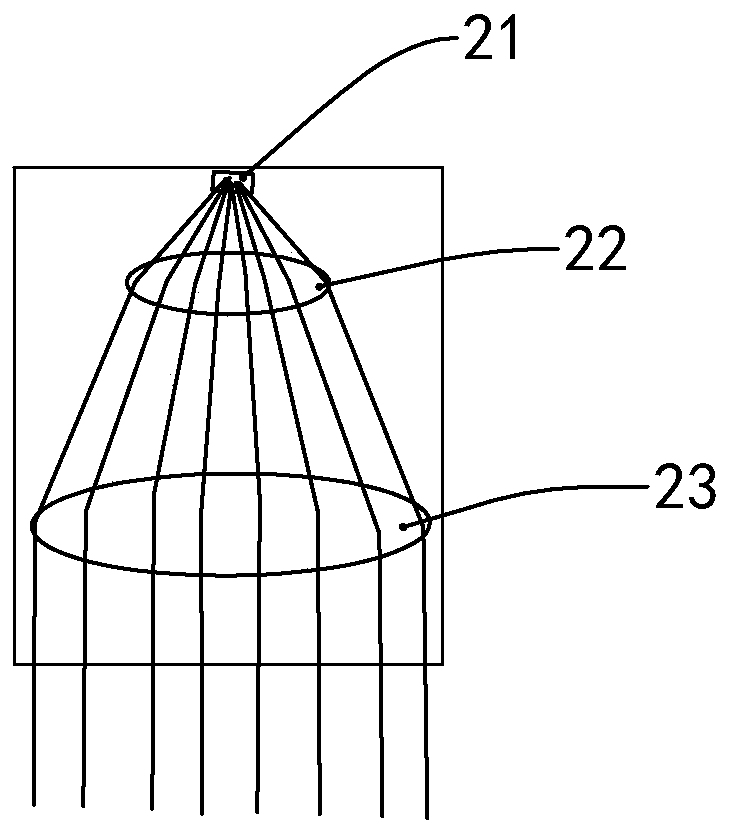
[0019] The laser emitting device 20...


PUM

PropertyMeasurementUnit
Thicknessaaaaaaaaaa

Abstract

The invention relates to a penetrating laser thickness gauge. The penetrating laser thickness gauge comprises a workbench and a laser emitting device, wherein the laser emitting device is used for emitting lasers; the workbench is used for placing a transparent part to be measured and provided with a notch. The penetrating laser thickness gauge also comprises a CCD detection device, the laser emitting device and the CCD detection device are respectively arranged on the two sides of the notch, lasers deviate from the normal line of the transparent part to be measured, and the CCD detection device is used for detecting the pixel displacement value on a plane after lasers pass through the transparent part to be measured. The penetrating laser thickness gauge has the advantage of high efficiency and accuracy.

Description

technical field [0001] The invention relates to the technical field of optical measurement, in particular to a penetrating laser thickness gauge. Background technique [0002] At present, the thickness of transparent glass materials in mobile phones, watches and tablet computers usually needs to be manually checked with calipers or dial gauges to control the accuracy. However, mainly affected by factors such as the use of measuring tools, the uniformity of force, and the measurement position, the data obtained by different people often differ greatly, resulting in large errors. At the same time, manual measurement is time-consuming and labor-intensive, with low production efficiency and high production costs. Contents of the invention [0003] Aiming at the deficiencies of the prior art, the object of the present invention is to provide an accurate and efficient penetrating laser thickness gauge. [0004] To achieve the purpose of the present invention, the present invent...

Claims


Application Information

Patent Timeline
IPC IPC(8): G01B11/06
CPCG01B11/06
Inventor 王和云
Owner 宾努克斯科技(佛山)有限公司
Features
  • R&D
  • Intellectual Property
  • Life Sciences
  • Materials
  • Tech Scout
  • Unparalleled Data Quality
  • Higher Quality Content
  • 60% Fewer Hallucinations
Learn More