
An anti-power plug for plant protection drones

A plant protection drone and plug technology, applied in the direction of circuits, electrical components, coupling devices, etc., can solve the problems of reverse connection between plug and socket, inconvenient disassembly, small contact area between plug and socket, etc., to improve power performance and stability sexual effect

Active Publication Date: 2021-01-29
ANHUI TIANDE INSTR TECH
View PDF6 Cites 0 Cited by
  • Summary
  • Abstract
  • Description
  • Claims
  • Application Information

AI Technical Summary

Problems solved by technology

[0002] At present, in the known electric-driven multi-rotor plant protection drones, the medicine box and the battery are fixedly connected to the body, and it is inconvenient to disassemble. The medicine box is filled with pesticides and the battery is charged. However, due to the limitation of the volume of the medicine box and the battery capacity, the ground preparation time for the unmanned aerial vehicle to go around is very long and frequent, which seriously affects the efficiency of pesticide spraying and improves the efficiency of plant protection. The cost of using the machine
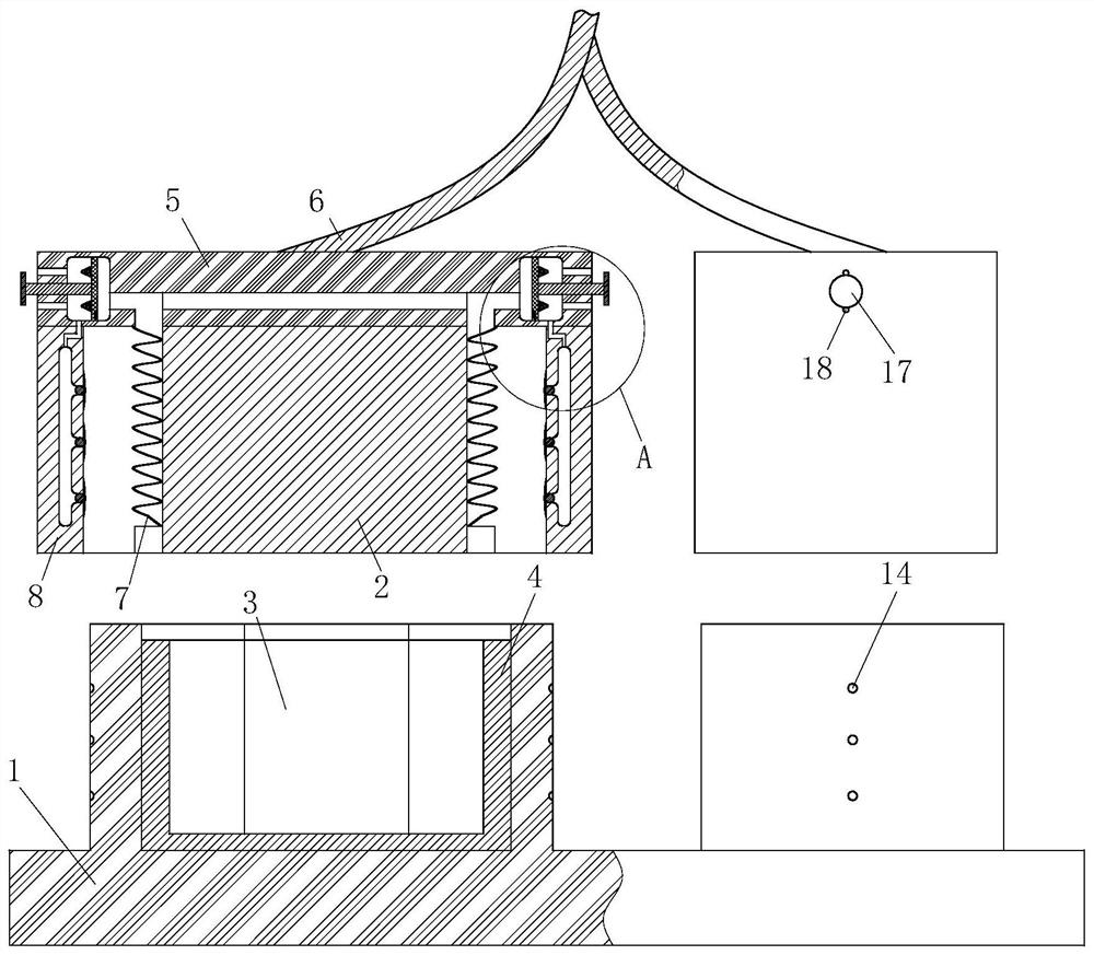
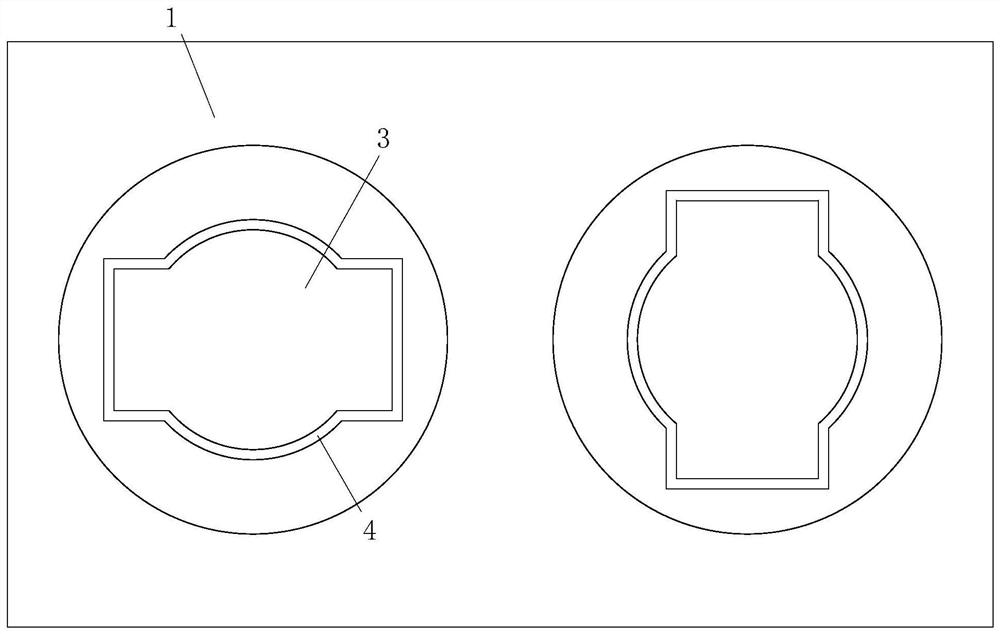
[0003] For this reason, a kind of drone has appeared in the prior art, which mainly realizes the long battery life of the plant protection drone by quickly replacing the battery and the medicine box, but when changing, it is easy to cause the plug and the socket to be reversed, and the plug and the socket The contact area is small, which affects the overall power supply. In view of this, the present invention provides an anti-power-off plug for plant protection drones, which mainly sets two wide middle and relatively vertical jacks on the socket. Prevent reverse connection, and at the same time increase the contact area between the two, ensuring greater power supply efficiency

Method used


Image

  • An anti-power plug for plant protection drones
  • An anti-power plug for plant protection drones
  • An anti-power plug for plant protection drones

Examples


Embodiment Construction

[0020] In order to make the technical means, creative features, goals and effects achieved by the present invention easy to understand, the present invention will be further described below in conjunction with specific embodiments.

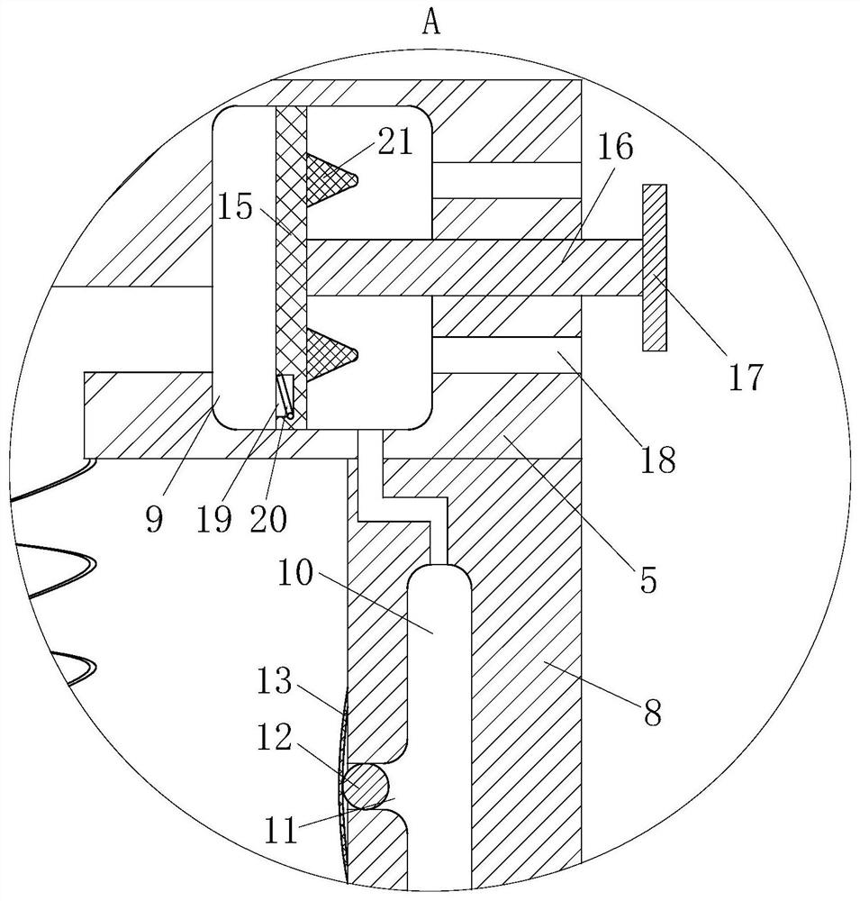
[0021] Such as Figure 1-3 As shown, an anti-power-off plug for plant protection drones according to the present invention includes a socket 1 and two plugs 2 matched therewith. The socket 1 is provided with two relatively vertical jacks 3 for plugging in The middle part of the hole 3 is wider than the two ends, the inner wall of the jack 3 is provided with a conductive plate 4, the top of the plug 2 is provided with an insulating seat 5, and the two insulating seats 5 are connected by a herringbone frame 6; during operation, the socket The two relatively vertical jacks 3 on 1 can be inserted into the two plugs 2 connected by the herringbone frame 6, and the two plugs 2 with opposite polarities can only be inserted from a fixed orientation until t...


PUM


Abstract

The invention belongs to the technical field of accessories for plant protection drones, in particular to a power-off prevention plug for plant protection drones; it includes a socket and two matching plugs, and the socket is provided with two relatively vertical plugs. The middle part of the jack is wider than the two ends, the inner wall of the jack is provided with a conductive plate, the top of the plug is provided with an insulating seat, and the two insulating seats are connected by a herringbone frame; the present invention sets two relatively vertical And the wider jack in the middle, the two relatively vertical jacks on the socket can be inserted into two plugs connected by a herringbone frame, and two plugs with opposite polarities can only be inserted into two plugs from a fixed orientation. In the jack with a larger middle width, the plug is prevented from being inserted backwards. At the same time, the middle width of each jack is larger than the width at both ends, which can make the contact area between the plug and the conductive plate larger, and provide power for a higher-power motor. , improving the power performance of the UAV.

Description

technical field [0001] The invention belongs to the technical field of accessories for plant protection drones, in particular to an anti-power-off plug for plant protection drones. Background technique [0002] At present, in the known electric-driven multi-rotor plant protection drones, the medicine box and the battery are fixedly connected to the body, and it is inconvenient to disassemble. The medicine box is filled with pesticides and the battery is charged. However, due to the limitation of the volume of the medicine box and the battery capacity, the ground preparation time for the unmanned aerial vehicle to go around is very long and frequent, which seriously affects the efficiency of pesticide spraying and improves the efficiency of plant protection. The cost of using the machine. [0003] For this reason, a kind of drone has appeared in the prior art, which mainly realizes the long battery life of the plant protection drone by quickly replacing the battery and the m...

Claims


Application Information

Patent Timeline
Patent Type & Authority Patents(China)
IPC IPC(8): H01R24/00H01R13/10H01R13/502H01R13/642H01R13/627H01R13/633H01R13/635
CPCH01R13/10H01R13/502H01R13/6276H01R13/633H01R13/635H01R13/642H01R24/00H01R2201/26
Inventor 尹建安杨桦杨鹏金用
Owner ANHUI TIANDE INSTR TECH
Learn More