Laser welding method

A laser welding and laser technology, applied in laser welding equipment, welding equipment, metal processing equipment, etc., can solve problems such as insignificant deformation

Active Publication Date: 2021-02-02
MITSUBISHI ELECTRIC CORP
View PDF13 Cites 0 Cited by
  • Summary
  • Abstract
  • Description
  • Claims
  • Application Information

AI Technical Summary

Problems solved by technology

Patent Document 1 discloses a method in which deformation is made inconspicuous by welding in a zigzag pattern during laser welding

Method used


Image

  • Laser welding method
  • Laser welding method
  • Laser welding method

Examples


Embodiment approach 1

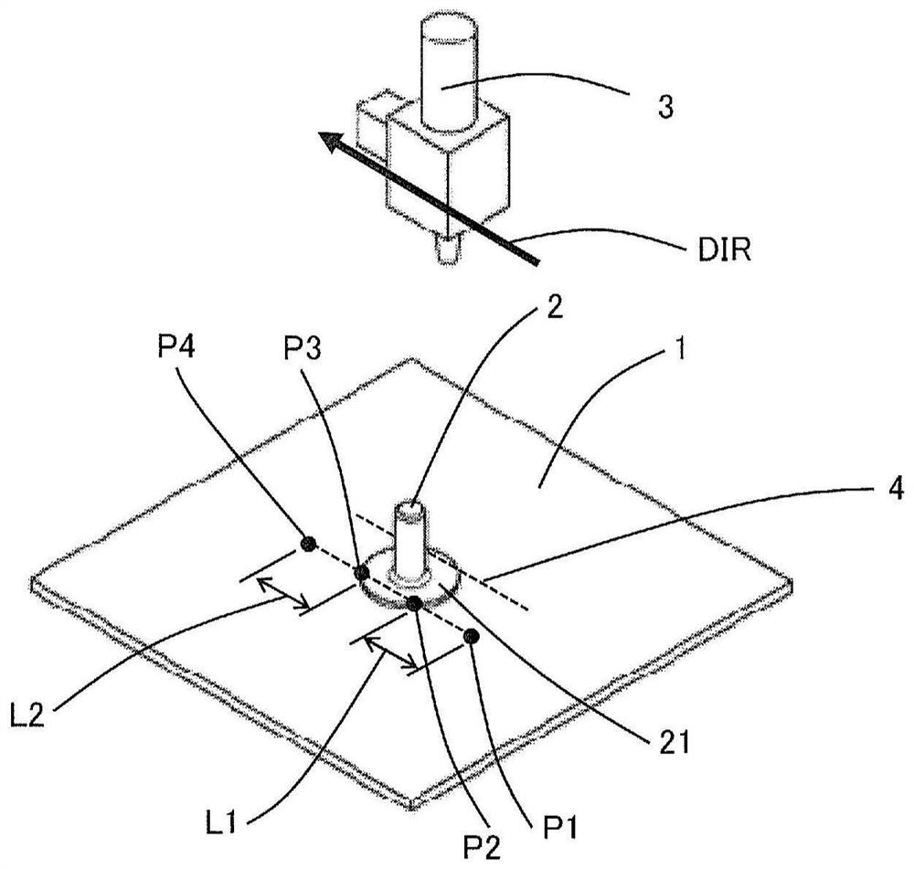
[0035] In Embodiment 1, an embodiment in which small parts such as studs are laser-bonded to a decorative material will be described. figure 1 It is a perspective view for demonstrating the laser welding method of the decoration material which concerns on Embodiment 1 of this invention. More specifically, the figure 1 It is a perspective view which shows the state which welds the stud 2 fixed to the decoration material 1 by the jig|tool, moving a laser welding head.

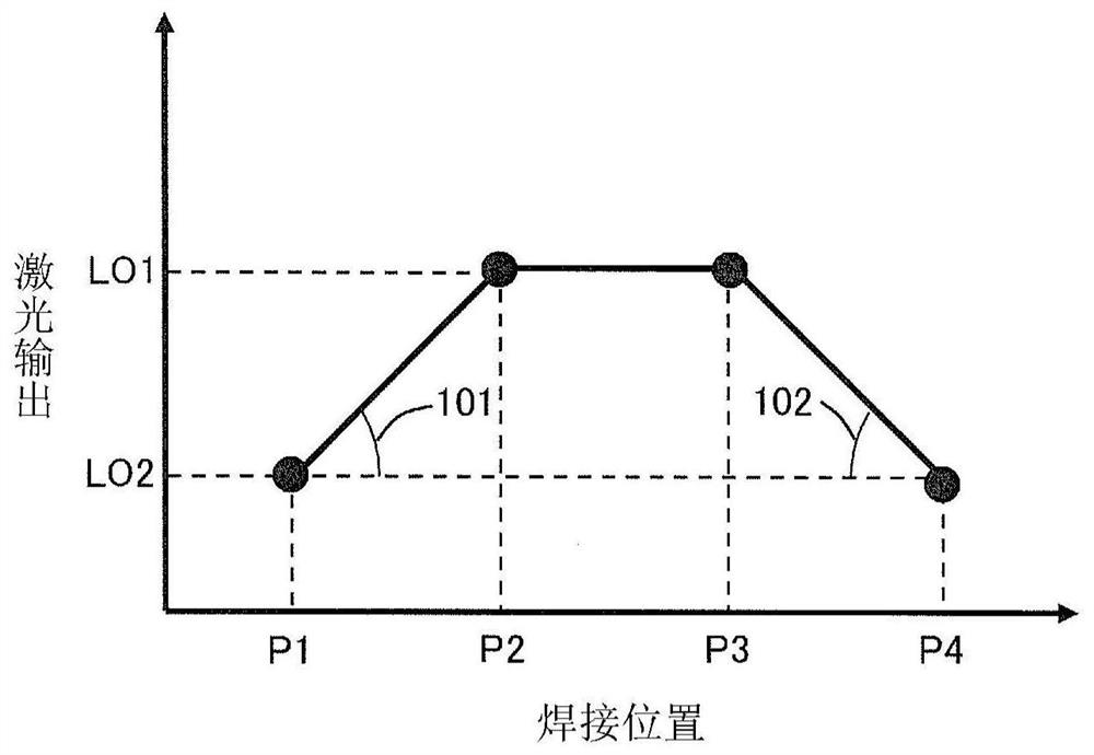
[0036] also, figure 2 It is a figure which shows the relationship of a welding position and a laser output when the laser welding method of the decoration material which concerns on Embodiment 1 of this invention is applied. use these figure 1 , figure 2 , and the laser welding method of the decorative material according to the first embodiment will be described in detail.

[0037] First, the laser welding head 3 moves to the welding start position P1 on the welding line 4 . The distance L1 between the we...

Embodiment approach 2

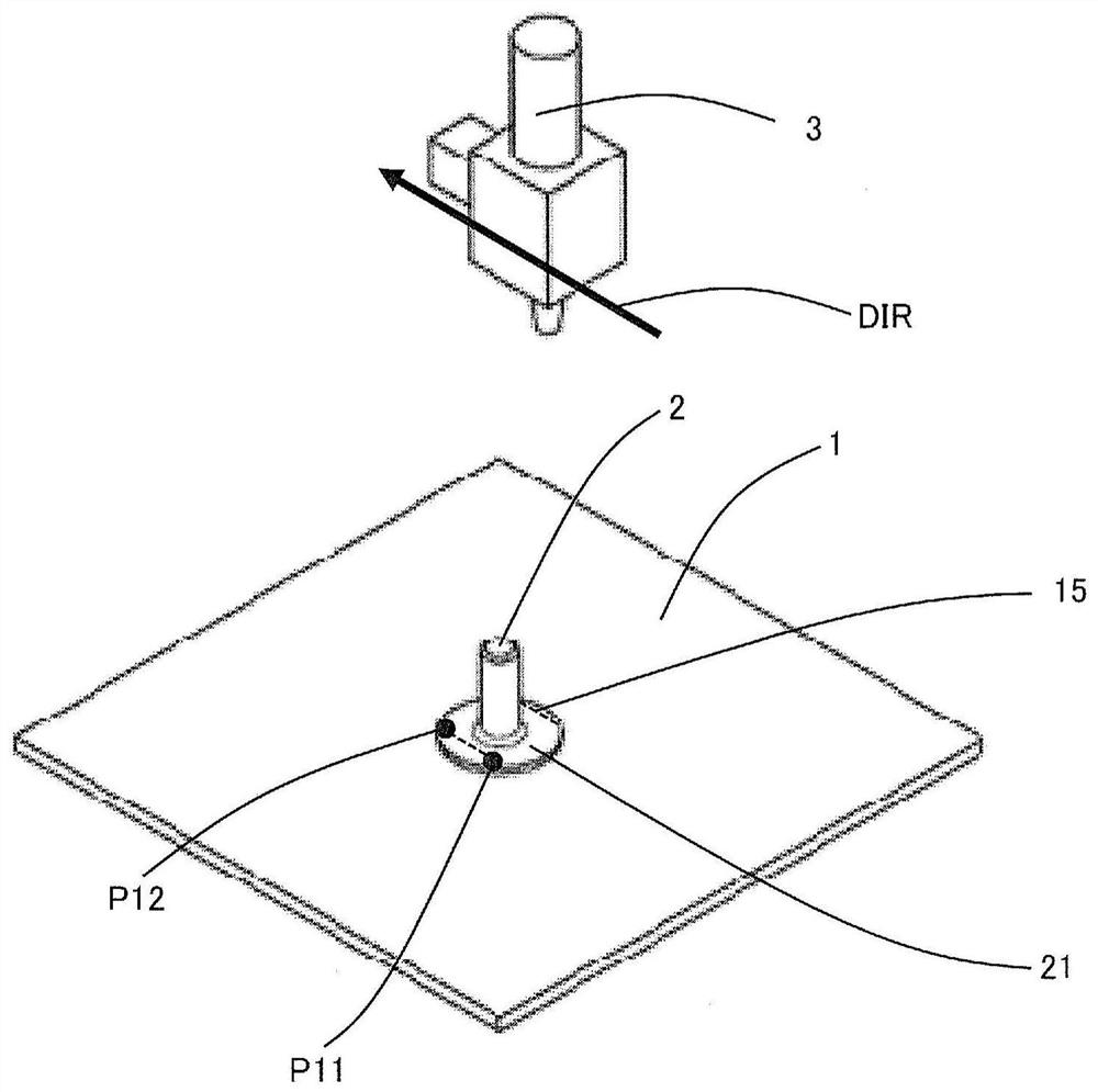
[0050] In Embodiment 2, the case where the first welding is performed in the flange 21, the size of the deformation is measured, and the value of the main laser output is set to an appropriate value based on the measurement result, is used as the second welding. For the second welding, the welding process described in the first embodiment above is carried out.

[0051] image 3 It is a perspective view for demonstrating the 1st welding of the laser welding method of the decorative material concerning Embodiment 2 of this invention. also, Figure 4 It is a perspective view for demonstrating the 2nd welding of the laser welding method of the decoration material which concerns on Embodiment 2 of this invention.

[0052] and, Figure 5 It is a figure which shows the relationship of a welding position and a laser output when the laser welding method of the decoration material which concerns on Embodiment 2 of this invention is applied. use these Figure 3 ~ Figure 5 , and the ...


PUM


Abstract

The laser welding method of the present invention has a welding step of performing laser welding along a welding path starting from the welding start position on the plate, passing through one end and the other end of the member to be welded, and starting from the welding start position on the plate. The welding end position is used as the end point, and the laser output is controlled to rise in the welding path from the welding start position to one end of the welded part, and the laser output is maintained at the welding path from one end of the welded part to the other end. The main laser output performs laser welding by controlling the laser output downward in the welding path from the other end of the member to be welded to the welding end position.

Description

technical field [0001] The present invention relates to a laser welding method capable of performing reliable welding without impairing aesthetics when laser welding a member to be welded to a plate such as a decorative material. Background technique [0002] In elevators and escalators, the aesthetics of parts that may catch human eyes are important. Therefore, deformation or denting of the decorative material used for the walls or the operating panel is not allowed. On the other hand, it is necessary to join studs or brackets on the back side of the trim material, and various joining techniques are used. [0003] As a specific joining method, there is a prior art that uses resistance welding. However, if resistance welding is used, the design surface will be deformed by welding heat. That is, the energy density of joining using resistance welding is lower than that of laser welding described later. Therefore, the melting amount becomes too large, and as a result, the d...

Claims


Application Information

Patent Timeline
Patent Type & Authority Patents(China)
IPC IPC(8): B23K26/21B23K26/00B23K26/24B23K26/60
CPCB23K26/00B23K26/24B23K26/21B23K26/60
Inventor 汤浅英治八木勇士
Owner MITSUBISHI ELECTRIC CORP
Why Eureka
Try Eureka