
Transformer pin flattening device

A technology of transformers and pressure plates, applied in the field of transformers, can solve problems such as reducing work efficiency, consuming a large amount of manpower, and hidden dangers to personnel safety, and achieve the effect of improving stability

Pending Publication Date: 2019-11-12
ANHUI HEHAN OPTOELECTRONICS TECH
View PDF0 Cites 0 Cited by
  • Summary
  • Abstract
  • Description
  • Claims
  • Application Information

AI Technical Summary

Problems solved by technology

However, when cutting the pins, if the manual operation is performed, due to the small size of the transformer and the large amount of use, the operation consumes a lot of manpower, which reduces the work efficiency; and when the pins are cut, the pins are easy to move around. Splashing is not easy to clean, and it will also bring hidden dangers to the safety of personnel, which is not conducive to extensive promotion and popularization

Method used


Image

  • Transformer pin flattening device
  • Transformer pin flattening device
  • Transformer pin flattening device

Examples


Embodiment Construction

[0019] The following will clearly and completely describe the technical solutions in the embodiments of the present invention with reference to the accompanying drawings in the embodiments of the present invention. Obviously, the described embodiments are only some, not all, embodiments of the present invention. Based on the embodiments of the present invention, all other embodiments obtained by persons of ordinary skill in the art without making creative efforts belong to the protection scope of the present invention.

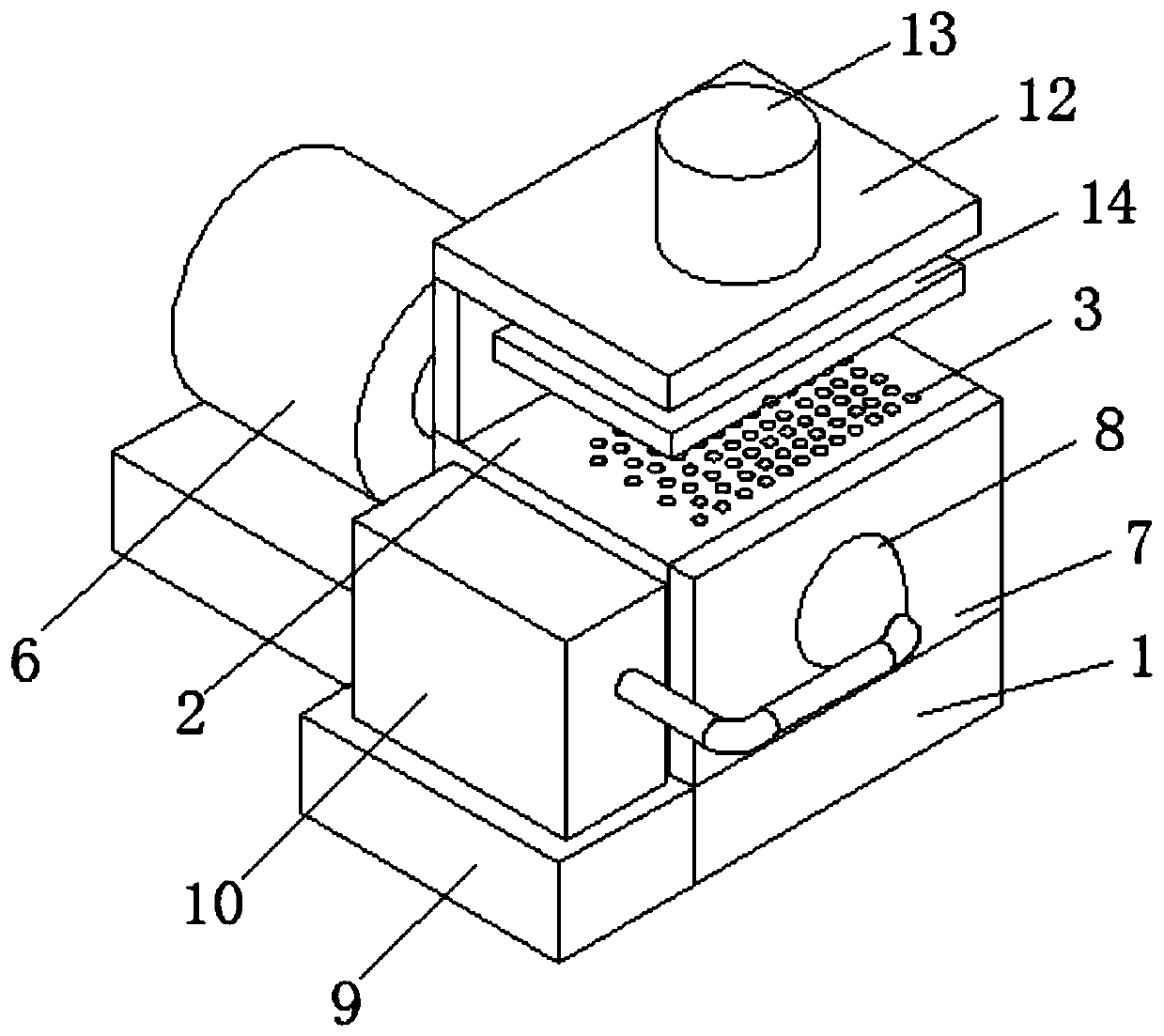
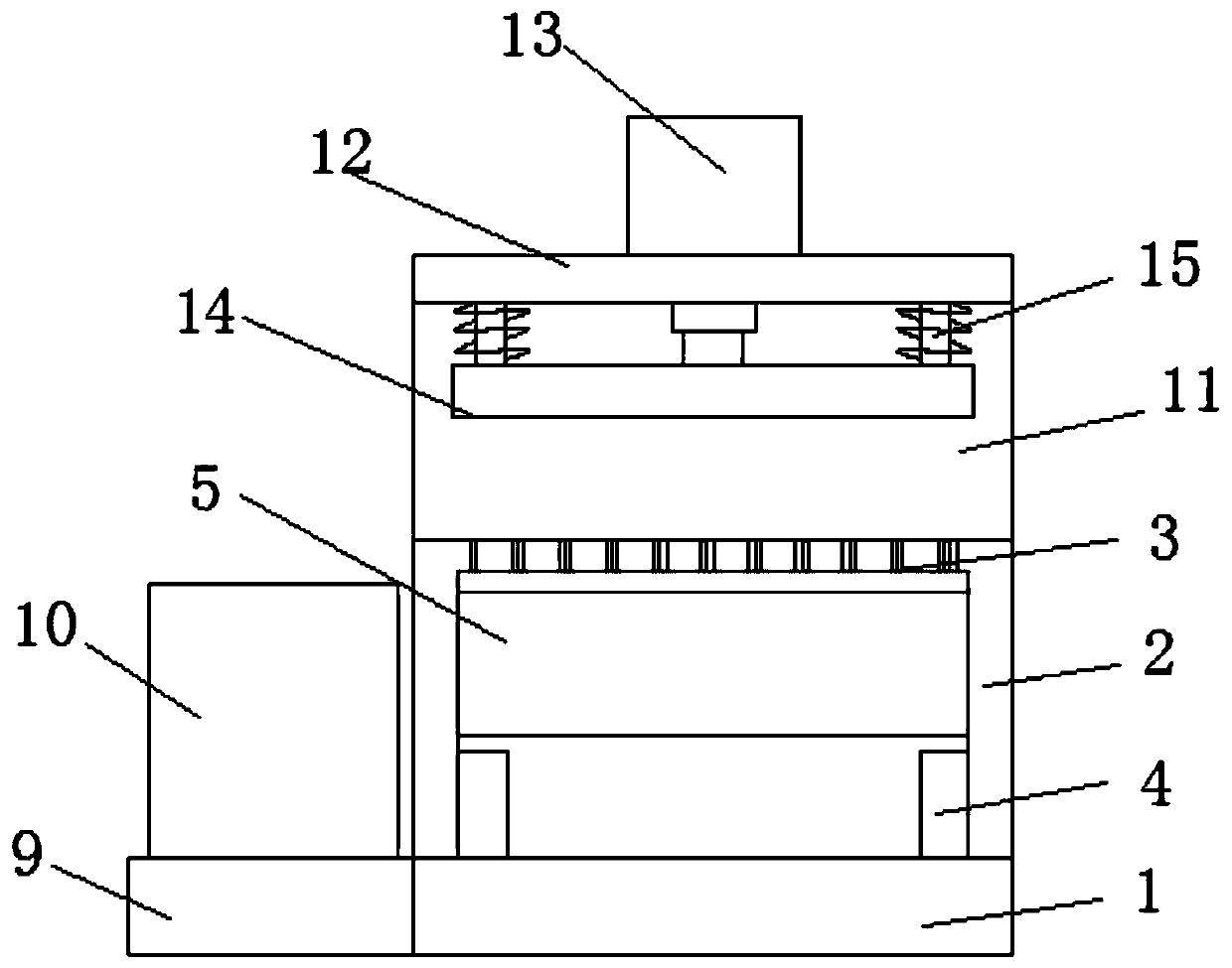
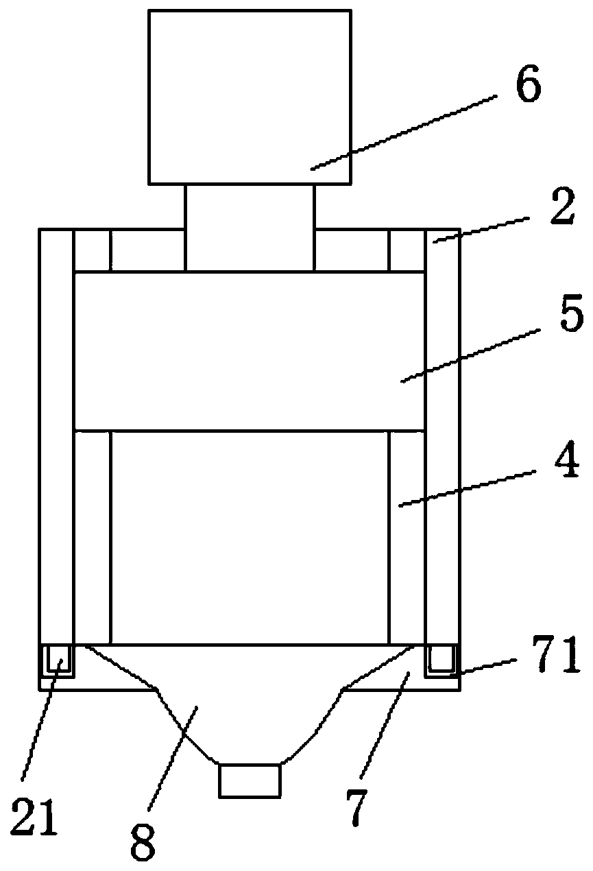
[0020] The present invention provides such Figure 1-3 The transformer pin flattening device shown includes a base 1, the top end of the base 1 is welded with a shell 2 that is not closed at both ends, and the top of the shell 2 is densely covered with through holes 3 for inserting the transformer pins, Sliders 4 are welded to the inner bottom ends of both sides of the housing 2, and the inside of the housing 2 is slidably connected to a metal block 5 at the t...


PUM


Abstract

The invention discloses a transformer pin flattening device. The transformer pin flattening device comprises a base, a shell which is not closed at the two ends is welded at one end of the top of thebase, through holes used for inserting transformer pins are densely distributed in the top of the shell, sliding blocks are welded to the bottom ends of the two sides of the interior of the shell, a metal block is connected in the interior of the shell and located at the top ends of the sliding blocks, a cylinder assembly is fixedly connected to the other end of the top of the base, a stand columnis welded to one end of the top of the shell, a cross beam is welded to the top of the stand column, an electric cylinder body is fixedly installed at the top of the cross beam, an output shaft of the electric cylinder body penetrates through the cross beam and is fixedly connected with a pressing plate, an end cover is movably installed at the front end of the shell, and a dust hood is installedin the surface of the end cover in an embedded mode. The device is simple and reasonable in structural design, convenient to operate, time-saving and labor-saving, capable of improving working efficiency, beneficial to the cleaning and recovering of waste materials, safe and stable, wide in application range and beneficial to popularization and popularization.

Description

technical field [0001] The invention belongs to the technical field of transformers, in particular to a transformer pin leveling device. Background technique [0002] Small transformers mainly refer to transformers with single-phase below 20kV·A and three-phase below 50kV·A, which are characterized by small size, low cost and few wires. The load rate and utilization rate of small transformers are generally low, and the inductive loads it carries are generally not capacitively compensated. Small transformers are a common equipment in the electrical control system of factories. With the large number of electronic components used in power plants Small transformers are increasingly used in control, monitoring and automation circuits. [0003] There are many pairs of pins on the transformer. Before the transformer is packaged or used, because the pins are of different lengths or too long, the pins on the transformer will be cut so that the pins are of the same length and Meet t...

Claims


Application Information

Patent Timeline
Patent Type & Authority Applications(China)
IPC IPC(8): B21F11/00B08B15/04
CPCB21F11/00B08B15/04
Inventor 夏云
Owner ANHUI HEHAN OPTOELECTRONICS TECH
Learn More