Laser measuring device

A laser measurement and laser technology, which is applied in the direction of measuring devices, instruments, particle and sedimentation analysis, etc., can solve the problems that affect the application range of laser particle size analyzers, and the accuracy of measurement results limited by optical energy density.

Active Publication Date: 2019-11-12
CHANGSHA QINGBO PHOTOELECTRIC TECH CO LTD
View PDF20 Cites 0 Cited by
  • Summary
  • Abstract
  • Description
  • Claims
  • Application Information

AI Technical Summary

Problems solved by technology

[0003] Existing laser particle size analyzers generally use a surface-emitting laser combined with a beam expander to expand the beam emitted by the surface-emitting laser through the beam expander to measure the particle size of the gas. The light energy density of the solid-state laser emitting in the direction of the bottom surface li

Method used


Image

  • Laser measuring device
  • Laser measuring device
  • Laser measuring device

Examples


Example Embodiment

[0028] In order to make the objectives, technical solutions and advantages of the present invention clearer, the present invention will be further described in detail below with reference to the accompanying drawings. Based on the embodiments of the present invention, those of ordinary skill in the art can obtain the results without creative work. All other embodiments of are within the protection scope of the present invention.

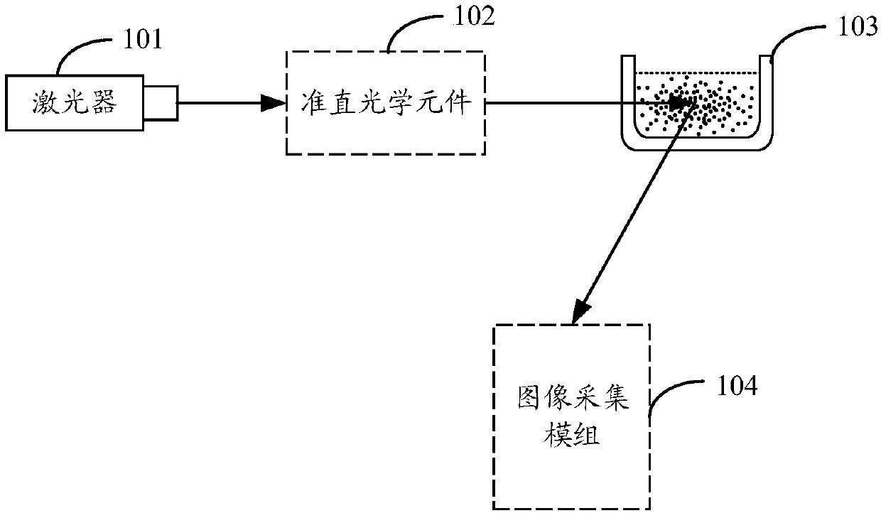
[0029] An embodiment of the present invention provides a laser measuring device, please refer to figure 1 , The laser measuring device includes: a laser 101, a collimating optical element 102, a liquid containing device 103 and an image acquisition module 104; the liquid containing device 103 is used to contain the liquid to be measured, the collimating optical element 102 and The image acquisition module 104 is located on the same side of the liquid storage device 103, and the liquid storage device 103 is located at the intersection of the central axis ...


PUM


Abstract

The embodiments of the invention disclose a laser measuring device. The device includes a laser, a collimating optical element, a liquid accommodating device and an image acquisition module. The liquid accommodating device is used for accommodating to-be-measured liquid. The collimating optical element and the image acquisition module are located at one side of the liquid accommodating device. Moreover, the liquid accommodating device is located at the intersection of a central axis of the collimating optical element and a central axis of the image acquisition module. The laser is arranged onone side of the collimating optical element and is used for emitting a laser beam. The collimating optical element is used for collimating the laser beam, and the collimated laser beam is emitted to the liquid accommodating device. The image acquisition module is used for acquiring a light spot image of scattered light formed after the laser beam is irradiated to the liquid accommodating device.

Description

technical field [0001] The invention relates to the technical field of instruments and meters, in particular to a laser measuring device. Background technique [0002] During the propagation of light, the wavefront is limited by pores or particles with a scale equivalent to the wavelength, and the emission of each elementary wave at the limited wavefront as the source interferes in space to produce diffraction and scattering, and the space of the diffracted and scattered light energy The (angular) distribution is related to the wavelength of light and the size of the pores or particles. Using a laser as a light source, the light is monochromatic light with a certain wavelength, and the spatial (angle) distribution of diffracted and scattered light energy is only related to the particle size. For the diffraction of particle groups, the number of particle levels determines the amount of light energy obtained at each specific angle, and the ratio of light energy at each specif...

Claims


Application Information

Patent Timeline
IPC IPC(8): G01N15/02
CPCG01N15/0211
Inventor 汪晓波
Owner CHANGSHA QINGBO PHOTOELECTRIC TECH CO LTD
Why Eureka
Try Eureka