
Optical path adjustable pipe phase holdup detection system and method

A detection system and a technology for phase holdup, which are used in the measurement of color/spectral properties, measurement devices, and material analysis by optical means. Reliable measurement and the effect of real-time online detection

Active Publication Date: 2019-11-12
HEBEI UNIVERSITY
View PDF5 Cites 0 Cited by
  • Summary
  • Abstract
  • Description
  • Claims
  • Application Information

AI Technical Summary

Benefits of technology

It describes methods that improve the precision and efficiency of detecting gases or liquids inside pipelines during their transport process. These techniques involve analyzing changes caused by factors like temperature differences between different parts of the pipeline's interior walls. By comparing these measurements against previous data from simulations, they suggest possible ways to enhance the quality control processes involved in the production chain. Additionally, there have been developed devices called CORIS (Critically Reversible Optically Refractive Solar System) systems that allow researchers to monitor fluid phases without physically touch them overcomes difficulties associated with traditional methods such as observing transparency through glass windows. Overall, these technologies aimed towards better understanding and monitoring complex flows within industrial facilities.

Problems solved by technology

This patents describes various methods or devices that can be applied to accurately determine if any material (gas liquid) flows have been taken into different phases during their production process. These techniques include but may also involve analyzing changes over time caused by these materials' interactions with eachother components inside the equipment being manufactured. Additionally, some current systems only work well within specific conditions where they were initially set up beforehand without considering factors like temperature fluctuate or pressure differences across them.

Method used


Image

  • Optical path adjustable pipe phase holdup detection system and method

Examples


Embodiment Construction

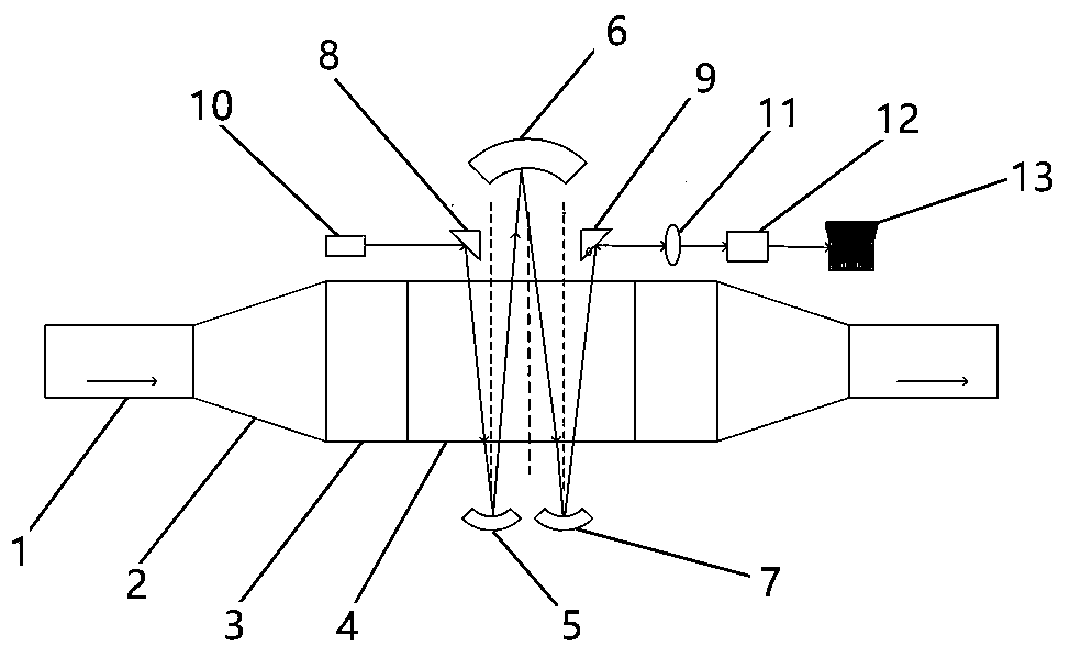
[0028] Such as figure 1 As shown, the detection system of the present invention includes a pipeline device, an optical path adjustment device, a light source transmitter, a signal receiving device, and a data acquisition and processing device.

[0029] The pipe installations from left to right are small diameter pipe 1, transition tapered pipe 2, large diameter pipe 3, organic glass pipe 4, large diameter pipe 3, transitional tapered pipe 2, small diameter pipe 1, and organic glass pipe 4 is Rectangular transparent pipes, the nozzles of other pipes are rectangular, and the joints are of matching size and sealed.

[0030] The phase holdup detection structure of the pipeline with adjustable optical path described in this paper, the internal diameter of the small diameter pipe is D 1 =50mm, tube body length L 1 =80mm, the wall thickness of the pipe body is 2mm; the length of the pipe body of the transition tapered pipe is L 2 =65mm; the inner diameter of the pipe of the large-...


PUM


Abstract

The invention provides an optical path adjustable pipe phase holdup detection system and method. The system comprises a pipe device, an optical path adjusting device, a light source emitter and a signal receiving device. The pipe device comprises an organic glass pipe located in the middle, and a large-diameter pipe, a transition tapered tube and a small-diameter pipe which are connected with twoends of the organic glass pipe in sequence. The optical path adjusting device comprises a first concave reflection mirror and a third concave reflection mirror which are set at the lower side of the organic glass pipe, and a first light guide mirror, a second concave reflection mirror and a second light guide mirror which are set in sequence at the upper side of the organic glass pipe. The first light guide mirror and the third concave reflection mirror are symmetrically set at two sides of a central axis of the second concave reflection mirror. The light source emitter is used for emitting visible light and near-infrared light. The system and the method are simple in structure. Free adjustment of an optical path is realized. The optical path is increased. A signal to noise ratio is improved. Measurement accuracy is improved. Real-time online detection can be realized.

Description


Claims


Application Information

Patent Timeline
Owner HEBEI UNIVERSITY
Learn More