A passive optical motion capture system camera correction control method and system

A correction control and camera technology, applied in the direction of using feedback control, etc., can solve the problems of cumbersome debugging and manual correction, etc., and achieve the effect of simplifying the workflow, solving the cumbersome manual correction, and reducing loss

Active Publication Date: 2022-03-25
FOSHAN UNIVERSITY
View PDF13 Cites 0 Cited by
  • Summary
  • Abstract
  • Description
  • Claims
  • Application Information

AI Technical Summary

Problems solved by technology

[0003] However, during the installation process of the motion capture system, it is necessary to manually adjust the orientation of each camera and the focal length of the lens. When there are too many cameras, debugging is very cumbersome
In addition, after moving the motion capture device or modifying the acquisition range of the motion capture system, it is also necessary to recalibrate the calibration
Therefore, the present invention provides a device to assist the correction work in the installation stage of the motion capture system, which solves the problem of cumbersome manual correction encountered during the installation process

Method used


Image

  • A passive optical motion capture system camera correction control method and system
  • A passive optical motion capture system camera correction control method and system

Examples


Embodiment Construction

[0025] The concept, specific structure and technical effects of the present disclosure will be clearly and completely described below with reference to the embodiments and accompanying drawings, so as to fully understand the purpose, solutions and effects of the present disclosure. It should be noted that the embodiments in the present application and the features of the embodiments may be combined with each other in the case of no conflict.

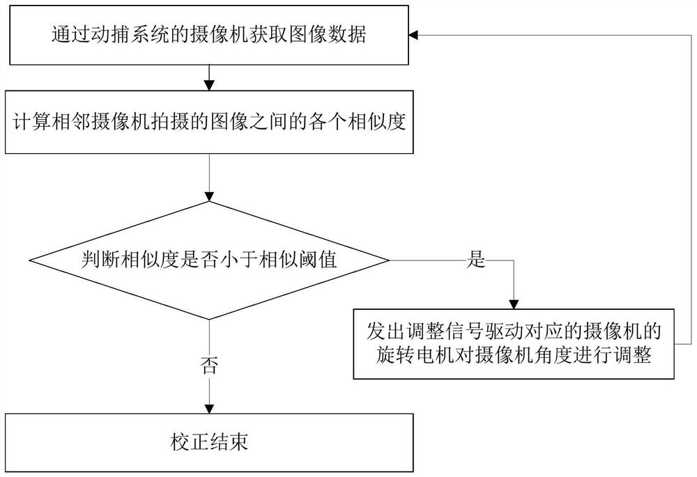
[0026] like figure 1 Shown is a flow chart of a camera correction control method for a passive optical motion capture system according to the present disclosure, which is combined below with figure 1 To illustrate a camera correction control method of a passive optical motion capture system according to an embodiment of the present disclosure.

[0027] The present disclosure provides a camera calibration control method for a passive optical motion capture system, which specifically includes the following steps:

[0028] Step 1, acquire...


PUM


Abstract

The invention discloses a camera correction control method and system of a passive optical motion capture system. Image data is acquired by a camera of the motion capture system, and each similarity between images captured by adjacent cameras is calculated. When the similarity is less than a similarity threshold, Send an adjustment signal to drive the corresponding camera's rotating motor to adjust the camera angle, and can remotely adjust the camera focal length to ensure image clarity. By adjusting the number of cameras used and reducing loss, the passive motion capture system calibration and calibration workflow can be simplified. , to achieve the purpose of providing users with a more convenient use environment and better equipment experience, and solve the problem of tedious manual correction during the installation process.

Description

technical field [0001] The present disclosure relates to the technical field of automatic control, in particular to a camera correction control method and system of a passive optical motion capture system. Background technique [0002] A typical optical motion capture system typically has 24 cameras arranged around the performance arena, and the area where the cameras' fields of view overlap is the performer's range of motion. For the convenience of processing, the performers are usually required to wear monochrome clothing, and stick some special signs or luminous points as capture marks on key parts of the body, and the visual system only recognizes and processes these marks. After that, the camera continuously shoots the performer's movements, saves the image sequence for analysis and processing, identifies the marker points and its spatial position in each frame, and then obtains the motion trajectory. [0003] During the installation of the motion capture system, it is...

Claims


Application Information

Patent Timeline
Patent Type & Authority Patents(China)
IPC IPC(8): G05D3/12
CPCG05D3/12
Inventor 曹明亮张浩洋
Owner FOSHAN UNIVERSITY
Why Eureka
Try Eureka