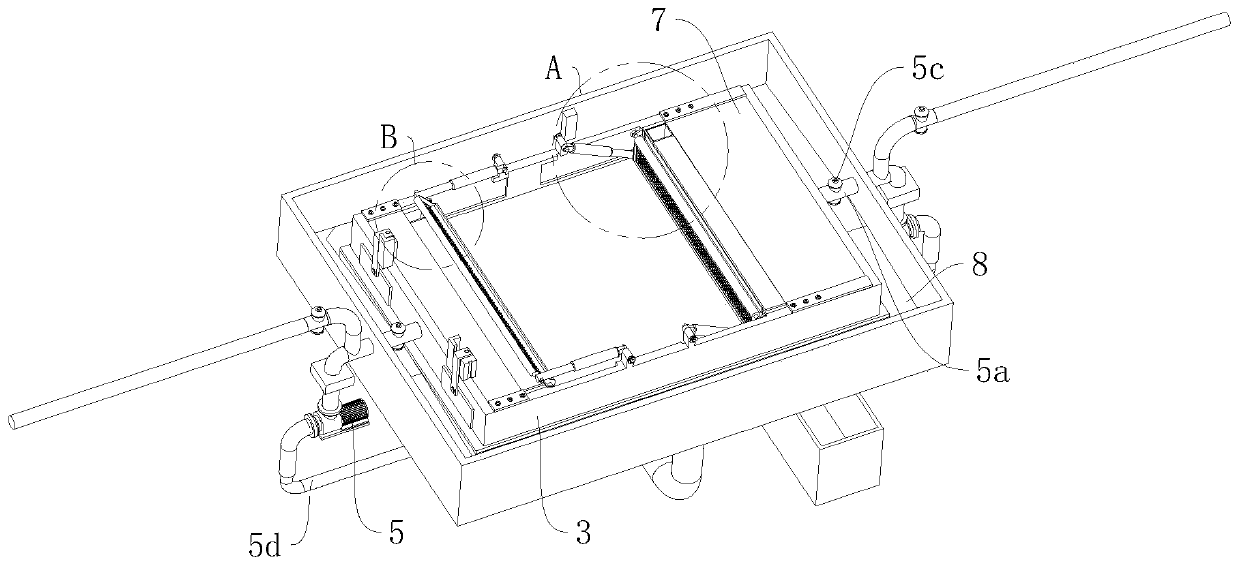
In-situ microbial purification device

A microbial purification, in-situ technology, which is applied in the feeding/discharging devices of sedimentation tanks, chemical instruments and methods, sedimentation tanks, etc., can solve the problems of insufficient sewage treatment speed, single structure, slow efficiency, etc.

Pending Publication Date: 2019-11-15
宁波国谱环保科技有限公司
View PDF0 Cites 2 Cited by
  • Summary
  • Abstract
  • Description
  • Claims
  • Application Information

AI Technical Summary

Benefits of technology

The present invent describes a system called Microbia® Paper Air Filter (MPF). It includes two main components - one is located near where there'reseals or bacteriostats can act like filters but with different functions depending upon their location. One component acts as a strain gauge while another helps keep them clean during use. Another part controls how much pressure goes towards each other when they move between these parts. A third section allows fluid to go around freely without getting trapped under gravity. These technical features help improve the performance of air filtrations systems such as septic tanks.

Problems solved by technology

This patented technical problem addressed by the current methods described above relates how to efficiently treat wastewater with nitrogen compounds while minimizing their impact on other areas such as fishing nets and aquatic ecosystems.

Method used


Image

  • In-situ microbial purification device
  • In-situ microbial purification device
  • In-situ microbial purification device

Examples


Embodiment Construction

[0036] A number of embodiments of the present invention will be disclosed in the following figures. For the sake of clarity, many practical details will be described together in the following description. It should be understood, however, that these practical details should not be used to limit the invention. That is, in some embodiments of the invention, these practical details are not necessary. In addition, for the sake of simplifying the drawings, some well-known and commonly used structures and components will be shown in a simple schematic manner in the drawings.

[0037]In addition, in the present invention, descriptions such as "first", "second" and so on are used for description purposes only, and do not refer to the meaning of order or sequence, nor are they used to limit the present invention, but are only for the purpose of distinguishing the following The components or operations described by the same technical terms are only used, but should not be understood as...


PUM


Abstract

The invention relates to the technical field of sewage treatment, and in particular relates to an in-situ microbial purification device. The device comprises two symmetrically-arranged aeration filters and a sedimentation tank arranged between the two aeration filters, the sedimentation tank has a horizontal-flow structure, the exterior of the sedimentation tank is provided with a circulation enclosure, and the circulation enclosure and the outer wall of the sedimentation tank constitute a dual-rectangular-shaped circulation cavity; the upstream and downstream ends of the sedimentation tank are respectively provided with one flow rectifying plate, each flow rectifying plate is provided with one corresponding mud passing conveying belt, the downstream end of each mud passing conveying beltis provided with one corresponding mud passing pipe, and opposite sides of the two flow rectifying plates are respectively provided with one mud intercepting plate; the upstream and downstream ends ofthe sedimentation tank are respectively provided with one circulation pump, a circulation pipeline communicating with the circulation cavity is arranged below the sedimentation tank, and two circulation pumps respectively communicate the circulation pipeline through one corresponding material pumping pipeline; and the upstream and downstream ends of the sedimentation tank are respectively provided with one open-close gate. The device provided by the invention can realize repeated sewage washing and speed up mud-water separation efficiency.

Description


Claims


Application Information

Patent Timeline
Owner 宁波国谱环保科技有限公司
Why Eureka
Try Eureka