
High-efficiency energy-saving dust removal equipment

A dust-removing equipment, high-efficiency and energy-saving technology, applied in the fields of dispersed particle separation, chemical instruments and methods, combined devices, etc., can solve the problem of fast replacement frequency of the filter screen, and achieve the effect of reducing the filter burden, prolonging the service life, and reducing the number of replacements.

Inactive Publication Date: 2019-11-15
南京爱默升能源技术有限公司
View PDF14 Cites 2 Cited by
  • Summary
  • Abstract
  • Description
  • Claims
  • Application Information

AI Technical Summary

Problems solved by technology

[0003] Existing dust removal equipment filters dust directly through the filter screen, resulting in a fast filter replacement frequency, which cannot effectively meet people's needs for energy conservation and environmental protection. Deficiencies in Current Practical Applications

Method used


Image

  • High-efficiency energy-saving dust removal equipment
  • High-efficiency energy-saving dust removal equipment
  • High-efficiency energy-saving dust removal equipment

Examples


Embodiment 1

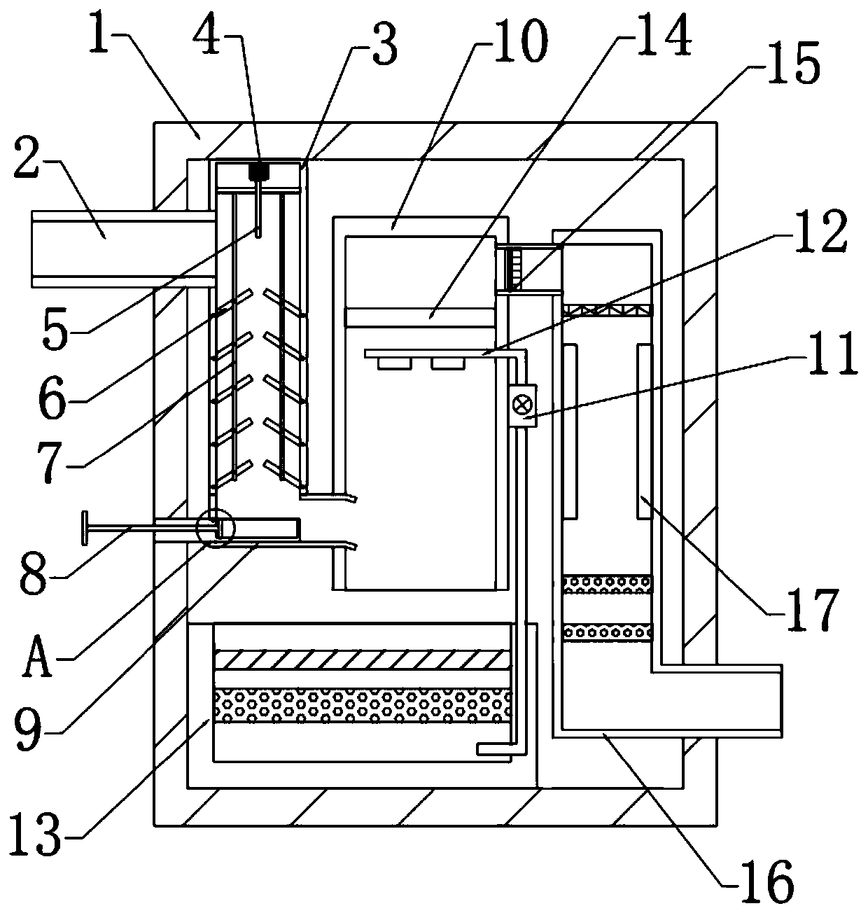
[0026] see Figure 1~3 , in an embodiment of the present invention, a high-efficiency energy-saving dust removal device includes a housing 1, an air intake pipe 2 is provided on the left side of the housing 1, the output end of the air intake pipe 2 is connected to a filter pipe 3, and the filter pipe 3 The top end is fixedly connected with the housing 1, a cleaning pipe 10 is arranged on the right side of the filter pipe 3, a connecting pipe 9 is arranged between the cleaning pipe 10 and the filter pipe 3, and the top of the right side of the cleaning pipe 10 is fixedly connected with a An air guide tube, the other end of which is connected to an air outlet tube 16, and a blower fan 15 is arranged in the air guide tube.

Embodiment 2

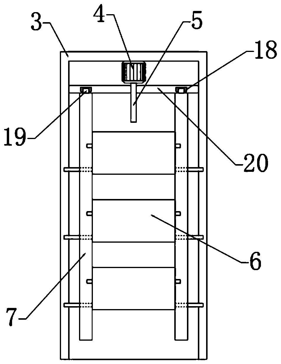
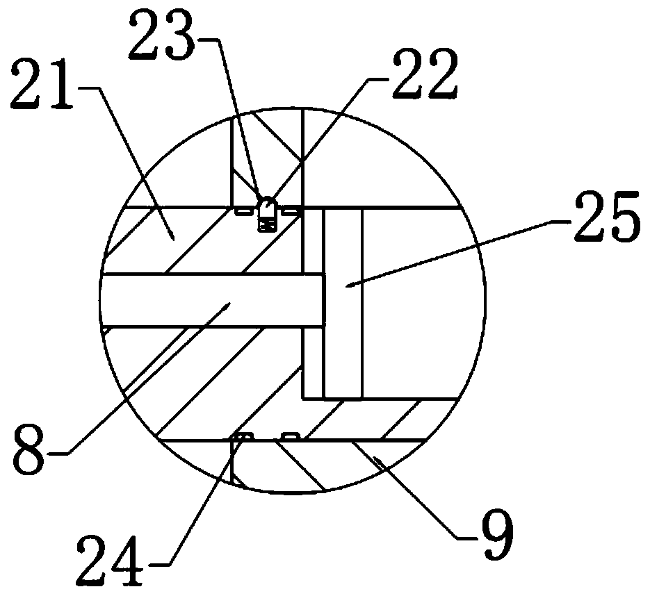
[0028] In this embodiment, a plurality of baffles 6 are hingedly arranged on the inner side of the filter tube 3, the front and rear sides of the baffles 6 are connected to the driving mechanism, and the lower side of the baffles 6 is provided with a dust collection mechanism. The dust collection mechanism is clamped with the connecting pipe 9.

[0029] In this embodiment, the drive mechanism includes a motor 4, a threaded rod 5 and a connecting rod 7, the motor 4 is bolt-connected and arranged on the inner top end of the filter tube 3, and the lower output end of the motor 4 is connected to the threaded rod 5, so Said threaded rod 5 outer thread connection is provided with the fixing plate 20 that is slidingly connected with the filter tube 3 pipe walls, and the front and rear sides of the bottom end of the fixing plate 20 are all slidingly connected to be provided with connecting rods 7, and the connecting rods 7 and the baffle plate 6 Hinged, by setting the driving mechanis...


PUM


Abstract

The invention relates to the technical field of environment-friendly equipment, in particular to high-efficiency energy-saving dust removal equipment. The equipment comprises a shell; a gas inlet pipeis arranged on the left side of the shell; the output end of the gas inlet pipe is connected with a filter pipe; a cleaning pipe is arranged at the right side of the filter pipe; a connecting pipe isarranged between the cleaning pipe and the filter pipe; the top of the right side of the cleaning pipe is fixedly connected with a gas guide pipe; and the other end of the gas guide pipe is connectedwith a gas outlet pipe. According to the invention, through the filter pipe, dust entering the equipment can be effectively collected, and the filter load of a filter screen is reduced, so that the service life of the filter screen is effectively prolonged, and replacement frequency are reduced; through arrangement of a dust collecting mechanism, people can conveniently take out the collected dust and treat the collected dust; and through arrangement of sterilizing lamps, air can be sterilized and disinfected while being subjected to dust removal, and quality of the air is greatly improved.

Description

technical field [0001] The invention relates to the technical field of environmental protection equipment, in particular to a high-efficiency energy-saving dust removal equipment. Background technique [0002] With the rapid development of science and technology, various industries continue to grow and develop, and the ensuing environmental problems are gradually emerging. my country's air pollution is becoming more and more serious, and the problem of dust emission from factories has been difficult to solve for a long time. Untreated industrial dust is directly or indirectly discharged into the atmosphere, which will not only endanger our health, destroy the ecological environment, but also seriously affect the environment. It affects the appearance of the city and hinders our process of building a beautiful home. Dust removal equipment refers to the equipment that separates dust from the air, also called dust collector. [0003] Existing dust removal equipment filters dus...

Claims


Application Information

Patent Timeline
Patent Type & Authority Applications(China)
IPC IPC(8): B01D50/00A61L9/18
CPCA61L9/18B01D50/10
Inventor 燕学博陈林
Owner 南京爱默升能源技术有限公司
Learn More