A stacked box casting method for horizontal pouring and two-way filling with split chilled iron plate molding

A technology of stacked box casting and iron plate, which is applied to casting molding equipment, cores, molds, etc., can solve the problems of affecting the casting efficiency of castings, restricting the casting efficiency, air bubbles, etc., and is conducive to rapid and uniform mold filling and casting. The effect of improving the yield and improving the utilization rate

Active Publication Date: 2021-08-13
GUANGXI YULIN LANGTAI AUTO PARTS
View PDF10 Cites 0 Cited by
  • Summary
  • Abstract
  • Description
  • Claims
  • Application Information

AI Technical Summary

Problems solved by technology

However, when iron mold sand casting is carried out on a flat, short, and cavity-free casting similar to a crankshaft bearing cap, the upper and lower molds covered with sand are combined and transported to the pouring table for pouring. In order to facilitate unpacking, pouring The process can only be carried out individually, and stacked boxes cannot be poured, which affects the casting efficiency of mass production of castings
[0003] At present, the pouring method of stacking sand core molding is to stack several layers of sand core molding vertically, and then pour molten iron through the sprue on the sand core molding; the existing pouring scheme cannot stack the sand core molding too high , which limits the number of stacked layers and casting efficiency. Moreover, when stacking vertically, when each layer of sand core is poured and filled, the air bubbles generated below will continue to rise up, which makes the probability of sand holes and slag holes higher.

Method used


Image

  • A stacked box casting method for horizontal pouring and two-way filling with split chilled iron plate molding
  • A stacked box casting method for horizontal pouring and two-way filling with split chilled iron plate molding
  • A stacked box casting method for horizontal pouring and two-way filling with split chilled iron plate molding

Examples


Embodiment Construction

[0025] The specific embodiments of the present invention will be described in detail below in conjunction with the accompanying drawings, but it should be understood that the protection scope of the present invention is not limited by the specific embodiments.

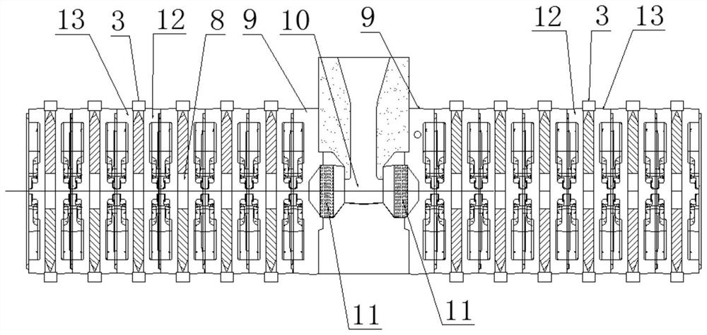
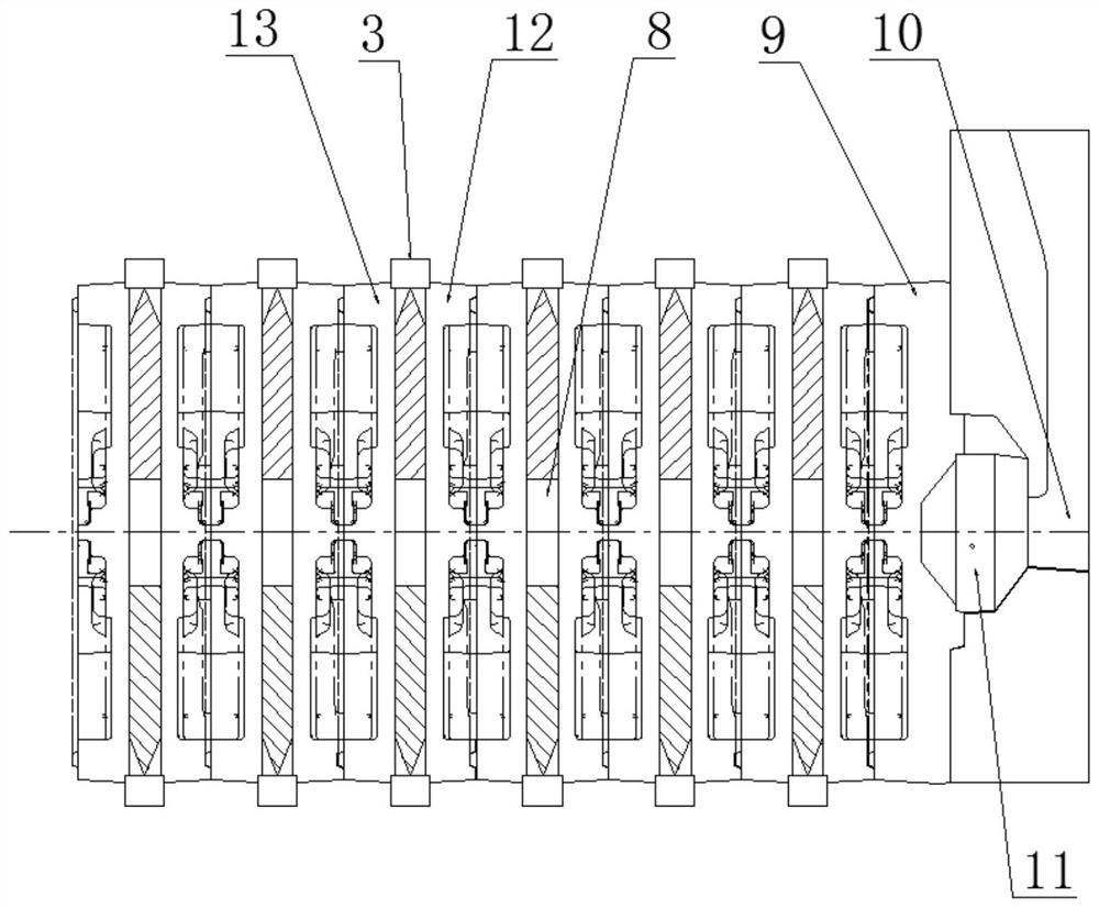
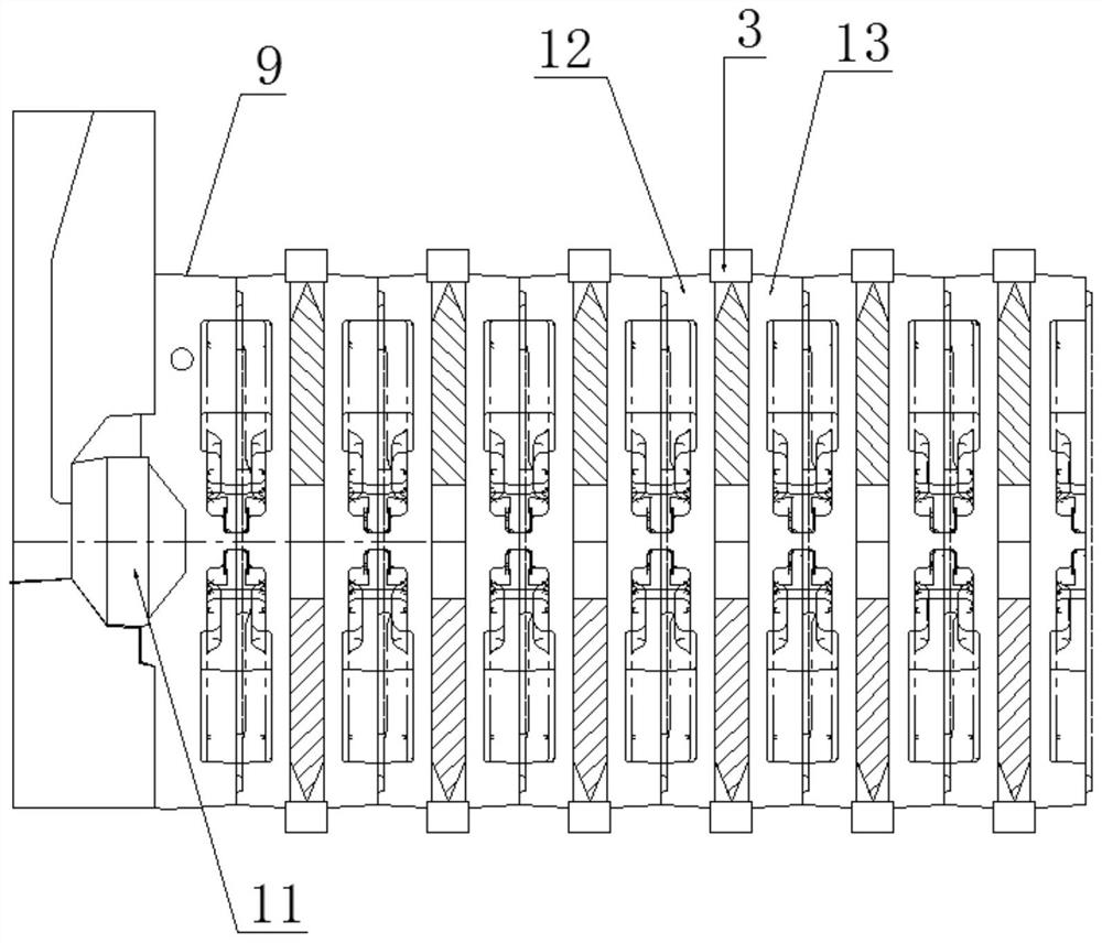
[0026] The specific embodiment of the present invention is like this: as Figure 1-8 As shown, a stacked box casting method using split chilled iron plates for horizontal pouring and two-way filling, the casting method includes: making a mold for making the first sand core 12 that is compatible with the structures on both sides of the casting, The second sand core 13, and the first sand core 12, the second sand core 13 have the first mold runner 6 and the second mold runner 7 respectively; a casting structure with a two-way gate 10 is set, and the second sand core 13 After the first sand core 12 and the second sand core 13 are mold-closed, several layers of sand molds are stacked horizontally on both sides with the two...


PUM


Abstract

The invention discloses a stacked box casting method for horizontal pouring and two-way filling with split chilled iron plate molding. The casting method includes: making a mold for making a first sand core matching the structures on both sides of the casting, The second sand core, and the first sand core and the second sand core are respectively provided with a first mold runner and a second mold runner; a pouring structure with a two-way gate is provided, and the first sand core and the second mold runner are provided. After the sand core mold is closed, several layers of sand molds are stacked horizontally on both sides with the two-way gate as the center. Separate cold iron plates are arranged between each layer of sand molds and clamped to each other. The molten iron is injected through the two-way gate of the pouring structure to The cavities in each layer of sand molds on both sides are poured horizontally. The stacked box casting method of the present invention adopts the horizontal pouring and bidirectional filling method of split chilled iron plates, adopts the method of horizontal pouring and bidirectional filling to stack boxes horizontally, and can double the number of stacked boxes compared with the traditional stacked box top pouring The number of layers greatly improves the utilization rate of molten iron, and the production cost of the sand box is greatly reduced.

Description

technical field [0001] The invention relates to the technical field of casting of engine components, more specifically, it relates to a stacked box casting method using split chilled iron plate molding for horizontal pouring and bidirectional filling. Background technique [0002] Since the iron mold sand-covered casting process can achieve riser-free casting and casting precision, its machining allowance is smaller compared with the sand casting process, the cleaning workload of the pouring system is less, and the cost is lower. When casting many castings, Usually iron sand casting is used. However, when iron mold sand casting is carried out on a flat, short, and cavity-free casting similar to a crankshaft bearing cap, the upper and lower molds covered with sand are combined and transported to the pouring table for pouring. In order to facilitate unpacking, pouring The process can only be carried out individually, and stacked boxes cannot be poured, thereby affecting the c...

Claims


Application Information

Patent Timeline
Patent Type & Authority Patents(China)
IPC IPC(8): B22C9/20B22C9/02B22C9/08B22D27/04
CPCB22C9/02B22C9/08B22C9/20B22D27/04
Inventor 韦明发梁红日
Owner GUANGXI YULIN LANGTAI AUTO PARTS
Why Eureka
Try Eureka