Shaft sleeve pressing system and sleeve pressing machine

A technology of sleeve pressing machine and shaft sleeve, which is applied in the direction of manufacturing tools, hand-held tools, etc., can solve the problems of sleeve shifting, interference, pressure judgment, etc., and achieve the effect of improving shaft sleeve shifting or shaft sleeve interference

Pending Publication Date: 2019-11-15
SANY HEAVY MACHINERY
View PDF0 Cites 0 Cited by
  • Summary
  • Abstract
  • Description
  • Claims
  • Application Information

AI Technical Summary

Problems solved by technology

The existing pressing machine cannot judge the pressure. The pressing process depends entirely on experience. When the size of the

Method used


Image

  • Shaft sleeve pressing system and sleeve pressing machine
  • Shaft sleeve pressing system and sleeve pressing machine

Examples


Embodiment Construction

[0028] In order to make the purpose, technical solutions and advantages of the embodiments of the present invention clearer, the technical solutions in the embodiments of the present invention will be clearly and completely described below in conjunction with the drawings in the embodiments of the present invention. Obviously, the described embodiments It is a part of embodiments of the present invention, but not all embodiments. The components of the embodiments of the invention generally described and illustrated in the figures herein may be arranged and designed in a variety of different configurations.

[0029] Accordingly, the following detailed description of the embodiments of the invention provided in the accompanying drawings is not intended to limit the scope of the claimed invention, but merely represents selected embodiments of the invention. Based on the embodiments of the present invention, all other embodiments obtained by persons of ordinary skill in the art wi...


PUM


Abstract

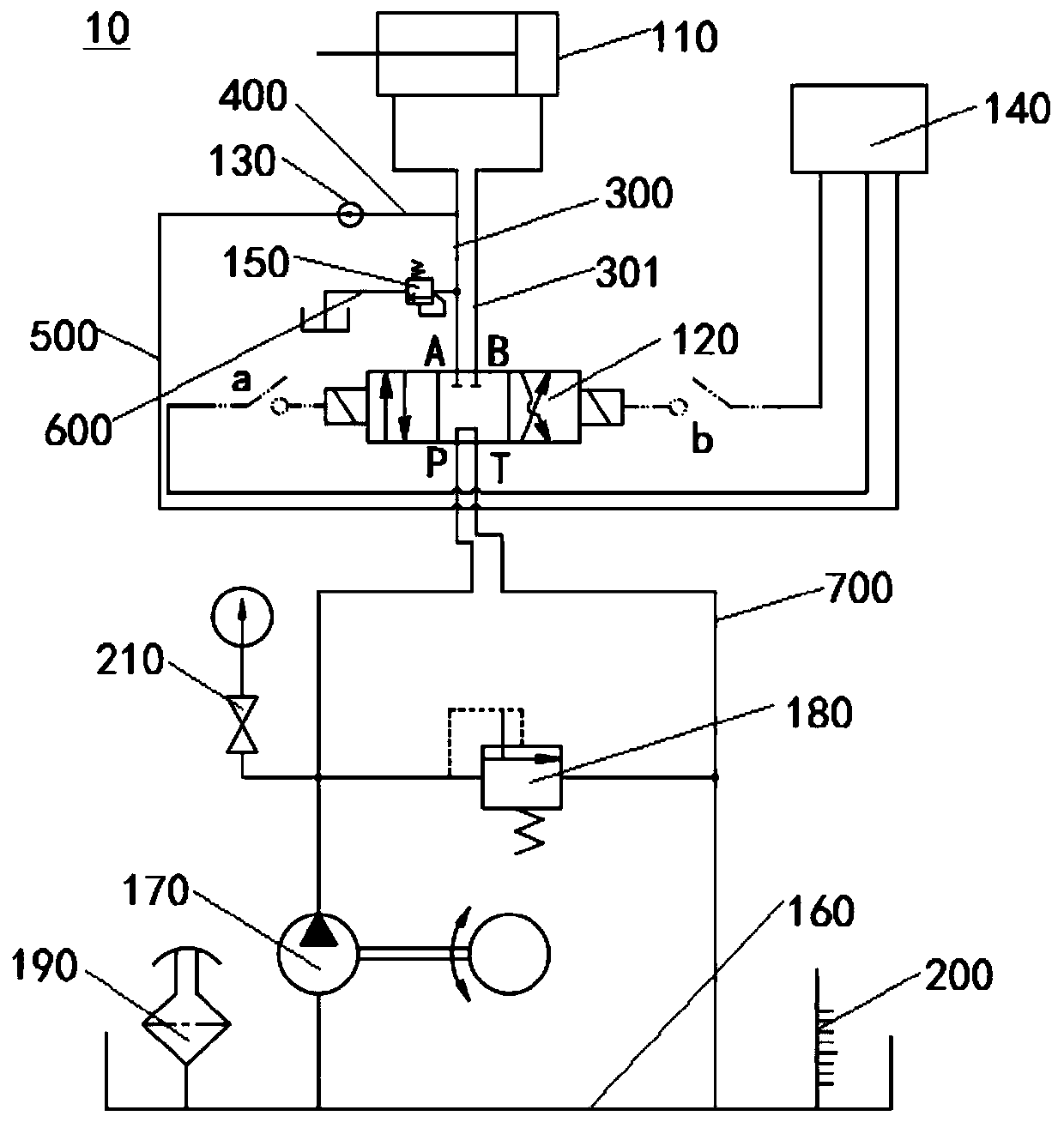
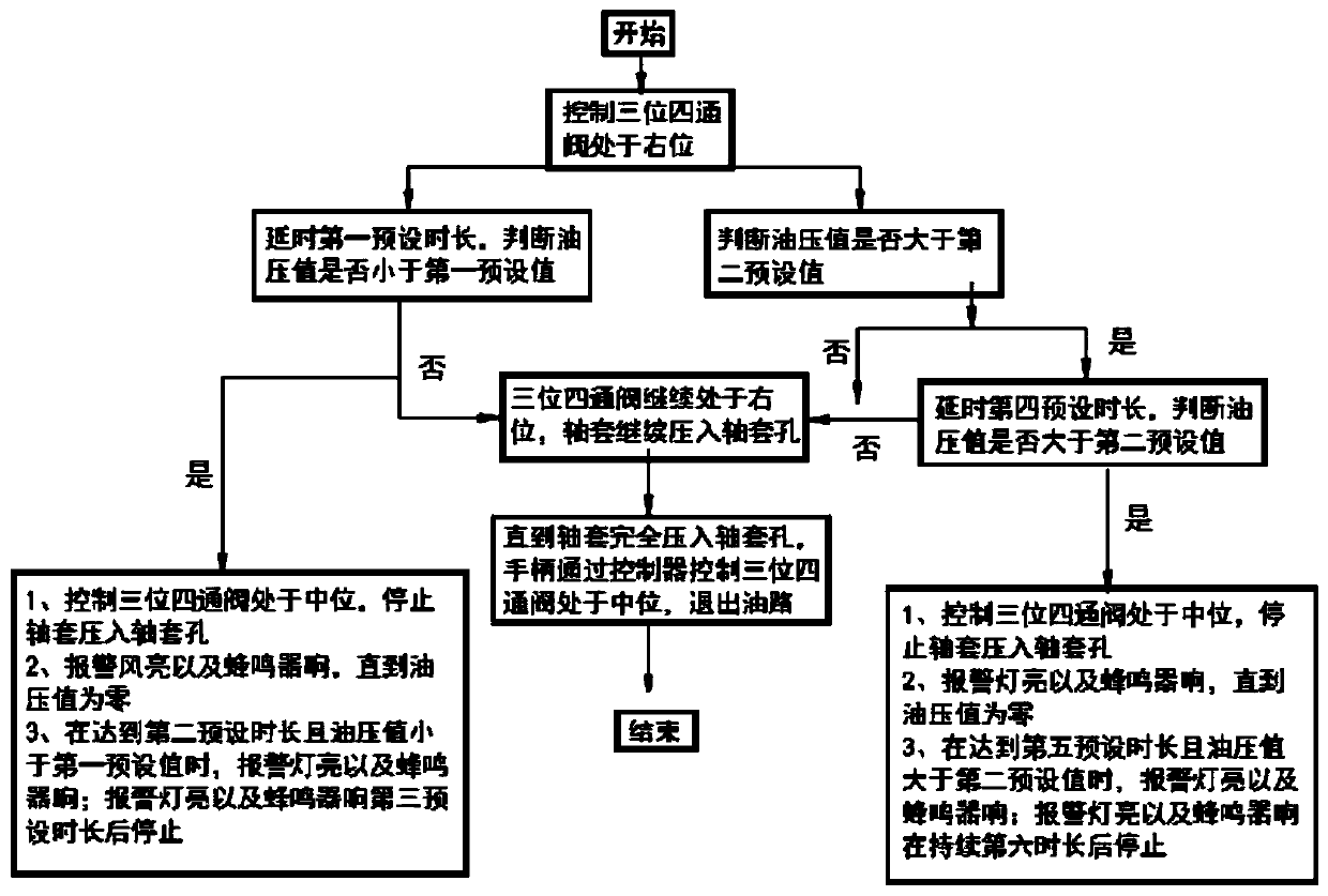
The embodiment of the invention provides a shaft sleeve pressing system and a sleeve pressing machine, relates to the technical field of shaft sleeve installation, and aims at solving the problem thatin the existing operation that a shaft sleeve is pressed into a shaft sleeve hole, shaft sleeve playing or shaft sleeve interference is likely to happen. The shaft sleeve pressing system comprises athree-position four-way valve, a sleeve pressing oil cylinder and a first branch. A pressure sensor is arranged on the first branch, a controller is used for receiving pressure signals which representthe oil pressure value and are sent by the pressure sensor, and the three-position four-way valve is in any state of the right position and the middle position. When the three-position four-way valveis located at the right position and oil enters a rod cavity of the sleeve pressing oil cylinder, the shaft sleeve is pressed in the shaft sleeve hole, the pressure sensor detects the oil inlet oil pressure of the rod cavity of the sleeve pressing oil cylinder, and when the oil pressure value is in the reasonable range, the controller controls the three-position four-way valve to be continuouslylocated at the right position, the shaft sleeve is continuously pressed in the shaft sleeve hole. When the oil pressure value exceeds the reasonable range, it is shown that the shaft sleeve and the shaft sleeve hole are not matched, the controller controls the three-position four-way valve to be located at the middle position, continuous pressing of the shaft sleeve into the shaft sleeve hole is stopped, and the fool-proof function is achieved.

Description

technical field [0001] The invention relates to the technical field of shaft sleeve installation, in particular to a shaft sleeve pressing system and a sleeve pressing machine. Background technique [0002] At present, the bushing of the working device (boom / stick) of construction machinery excavator is pressed into the bushing hole by a special pressing machine. As long as there is output pressure when the pressing machine is working, the bushing cylinder will start to work to press the bushing Press into the bushing hole. The existing pressing machine cannot judge the pressure, and the pressing process depends entirely on experience. When the size of the bushing hole is out of tolerance, it will cause the problem of bushing shifting or bushing interference after the bushing is pressed. Contents of the invention [0003] The purpose of the present invention includes, for example, to provide a bushing pressing system, which can improve the problem that the existing bushin...

Claims


Application Information

Patent Timeline
IPC IPC(8): B25B27/06
CPCB25B27/064
Inventor 孙国印尚沙沙肖高锋
Owner SANY HEAVY MACHINERY
Why Eureka
Try Eureka