A direct-boost double-fed switched reluctance generator converter system

A switched reluctance, direct boost technology, applied in the direction of controlling generators through magnetic field changes, can solve problems such as reducing power generation efficiency, and achieve the effects of improving efficiency and reliability, saving boost links, and stabilizing power quality output.

Active Publication Date: 2021-03-26
浙江知多多网络科技有限公司
View PDF7 Cites 0 Cited by
  • Summary
  • Abstract
  • Description
  • Claims
  • Application Information

AI Technical Summary

Problems solved by technology

[0008] In addition, the loss of the power electronic converter system has always been concerned by the industry, and the switching loss of the switching tube of the switched reluctance generator converter system is also one of the problems that reduces the overall power generation efficiency

Method used


Image

  • A direct-boost double-fed switched reluctance generator converter system

Examples


Embodiment Construction

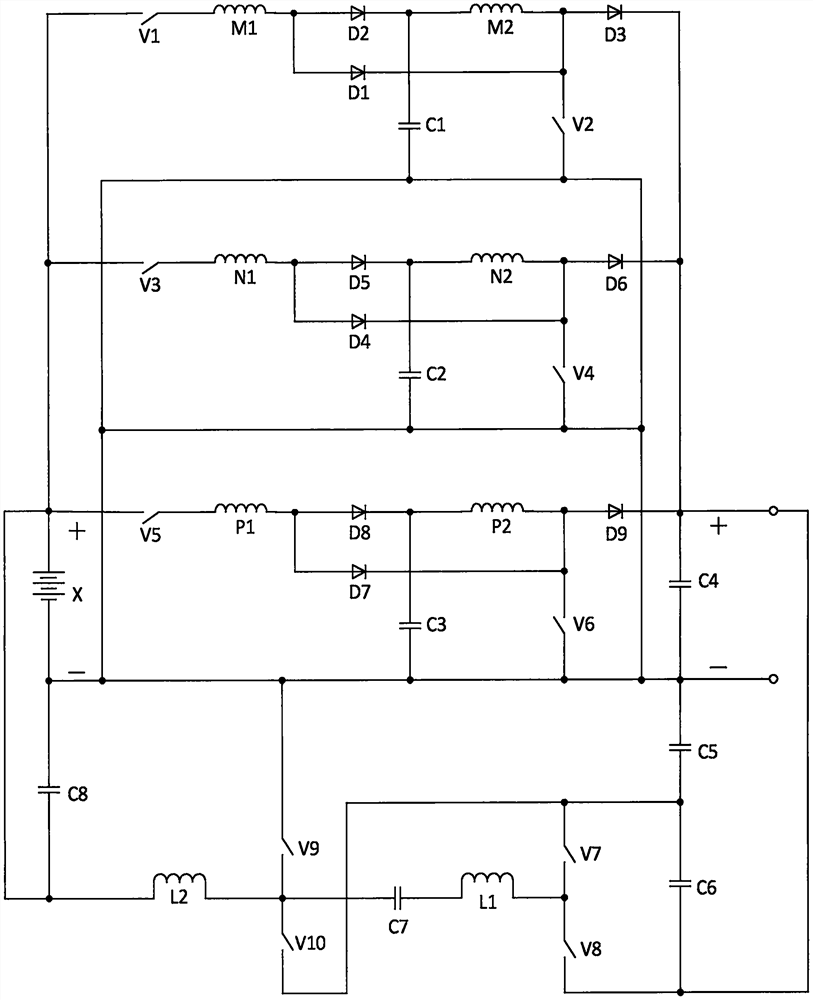
[0029] In this embodiment, a direct-boost double-fed switched reluctance generator converter system, the circuit structure of the converter system is as follows figure 1 As shown, it consists of battery X, first switch tube V1, second switch tube V2, third switch tube V3, fourth switch tube V4, fifth switch tube V5, sixth switch tube V6, seventh switch tube V7, The eighth switch tube V8, the ninth switch tube V9, the tenth switch tube V10, the first branch winding M1 of the first phase winding, the second branch winding M2 of the first phase winding, the first branch winding N1 of the second phase winding, the second The second branch winding N2 of the phase winding, the first branch winding P1 of the third phase winding, the second branch winding P2 of the third phase winding, the first diode D1, the second diode D2, the third diode D3, the third Four diodes D4, fifth diode D5, sixth diode D6, seventh diode D7, eighth diode D8, ninth diode D9, first capacitor C1, second capac...


PUM


Abstract

The invention relates to a direct-boosting doubly-fed switched reluctance generator current transformation system, which is composed of a storage battery, ten switch tubes, a three-phase winding, ninediodes, eight capacitors and two inductors, and is characterized in that the total output voltage is boosted directly under the condition of parallel connection of each phase output while the excitation and power generation of each phase winding, the problems of strengthened excitation and simultaneous work of two phase windings are solved at the same time, the switch tubes are not additionally increased, and the separated excitation storage battery can be automatically charged. Meanwhile, an automatic charging current transformation loop is utilized and can carry out backward feedback energyfeed after only fine adjustment, so that the cost performance and the adaptability are greatly improved, and the whole system is low in switching loss and high in output electric energy. The direct-boosting doubly-fed switched reluctance generator current transformation system is applicable to the field of low-power high-speed switched reluctance generator systems with various power inputs.

Description

technical field [0001] The invention relates to the field of switched reluctance motor systems, in particular to a switched reluctance generator transformer with direct parallel connection of high voltage output, enhanced excitation, automatic charging and reverse energy feedback, adapting to simultaneous operation of two-phase windings, low loss, and high power quality. Flow system and its control method. Background technique [0002] As a new type of power generation system, the switched reluctance generator system has attracted more and more attention from the industry due to its advantages of low cost and high fault tolerance, but its converter system is the heart of its work, which greatly affects its value. , performance improvement, and its variable flow system has developed slowly over the years. [0003] Switched reluctance generators generally directly generate DC power, which often cannot meet the needs of load or grid connection in terms of voltage. Therefore, s...

Claims


Application Information

Patent Timeline
Patent Type & Authority Patents(China)
IPC IPC(8): H02P9/30
CPCH02P9/30
Inventor 孙冠群蔡慧孙丽宏
Owner 浙江知多多网络科技有限公司
Why Eureka
Try Eureka