Modular battery replacing cabinet and maintenance method thereof

A modular and electric cabinet technology, applied in charging stations, current collectors, electric vehicles, etc., can solve problems such as inconvenient use for users, lower operating income, and difficulty in raising production capacity, so as to improve production and assembly efficiency and improve operation Efficiency, the effect of improving maintenance efficiency

Pending Publication Date: 2019-11-19
SHENZHEN COMPTON TECH
View PDF0 Cites 4 Cited by
  • Summary
  • Abstract
  • Description
  • Claims
  • Application Information

AI Technical Summary

Problems solved by technology

[0003] Defect 1: All the maintenance and assembly are done by opening the door at the back, which leads to the need to add space to the back when selecting points for product installation, and cannot be installed against the wall
If it is installed and maintained against the wall, it needs to use a large handling tool (such as a forklift) to move it. It is not only very inconvenient to reset after maintenance, but also the maintenance cost is quite high.
[0004] Defect 2: At present, if the product fails, it can only be maintained at the place where the product is installed. Once a failure occurs, it can only continue to operate after maintenance. This is not convenient for users, but also reduces operating income.
[0005] Defect 3: At present, the products in the industry are all installed with an overall structure. Due to the need to minimize the overall size of the cabinet, the internal space of the product is relatively small, which leads to only one person operating during the assembly process. Due to the large number of internal lines, the production capacity is difficult. lift up

Method used


Image

  • Modular battery replacing cabinet and maintenance method thereof
  • Modular battery replacing cabinet and maintenance method thereof
  • Modular battery replacing cabinet and maintenance method thereof

Examples


Embodiment Construction

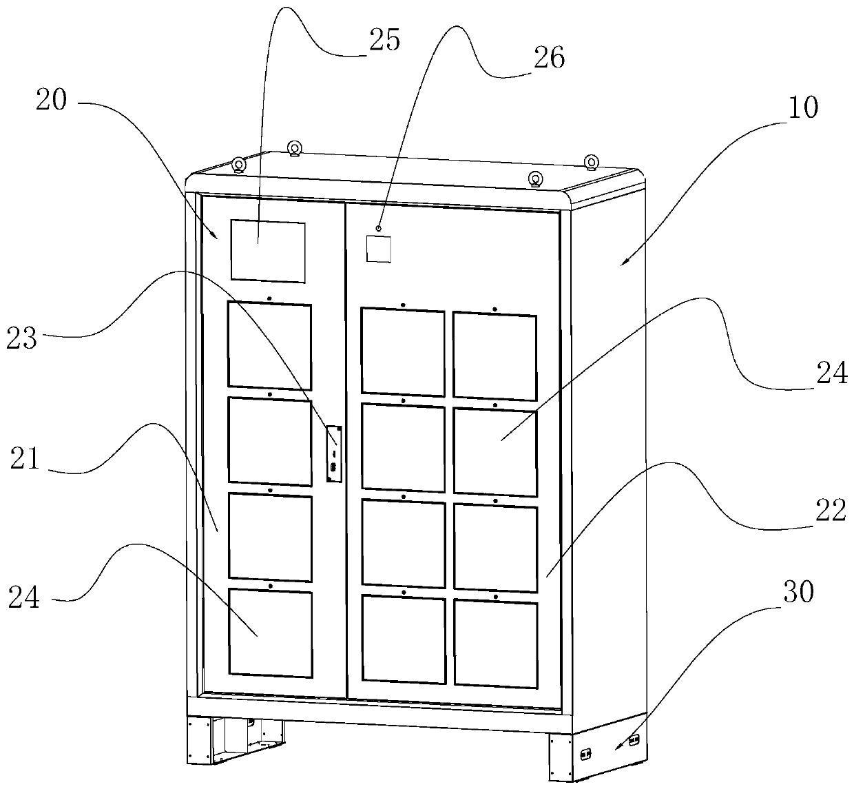
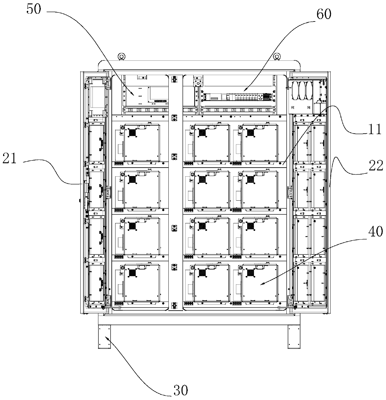
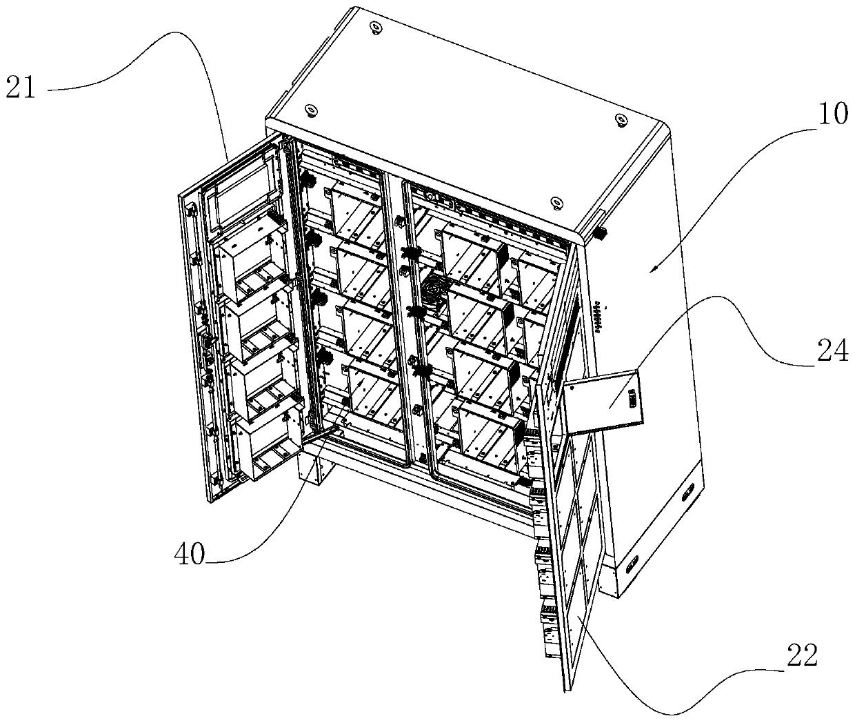
[0032] In order to make the purpose, technical solution and advantages of the present invention clearer, the present invention will be further described in detail below in conjunction with the accompanying drawings and specific embodiments.

[0033] The following will clearly and completely describe the technical solutions in the embodiments of the present invention with reference to the accompanying drawings in the embodiments of the present invention. Obviously, the described embodiments are only some, not all, embodiments of the present invention. Based on the embodiments of the present invention, all other embodiments obtained by those skilled in the art without creative efforts fall within the protection scope of the present invention.

[0034] In describing the present invention, it is to be understood that the terms "center", "longitudinal", "transverse", "length", "width", "thickness", "upper", "lower", "front", " Orientation or position indicated by "back", "left", "r...


PUM


Abstract

The invention discloses a modular battery replacing cabinet and a maintenance method thereof. The battery replacing cabinet comprises a cabinet body and a plurality of electric changing warehouse receipt units arranged in the cabinet body. The cabinet body is internally provided with a charging bracket, a plurality of power changing card positions are arranged on the charging bracket in array, thepower changing card positions are provided with power changing interfaces, and the electric changing warehouse receipt units are detachably mounted on the power changing card positions and connectedelectrically with the power changing interfaces. According to the electric changing cabinet, through the unitization singly of the electric changing warehouse receipt units, all the electric changingwarehouse receipt units are connected to the cabinet body quickly in a mounted mode through a connection terminal independently, the production and assembly efficiency of the battery replacing cabinetis greatly improved, when the electric changing warehouse receipt units fail, the problematic electric changing warehouse receipt units can be directly taken out for replacement, the maintenance efficiency is improved, and the operation efficiency of the battery replacing cabinet is improved; and a requirement for the location of the battery replacing cabinet is reduced, at the same time, when the battery replacing cabinet needs maintenance, the battery replacing cabinet does not need to be moved, and the maintenance efficiency of the battery replacing cabinet is further improved.

Description

technical field [0001] The invention relates to the field of charging devices, and more specifically relates to a modular power exchange cabinet and a maintenance method thereof. Background technique [0002] With the development of urban express delivery and takeaway business, the daily charge and discharge times of lithium battery electric vehicles have increased. According to the country's requirements for the charging and discharging of electric vehicles, the power exchange cabinet products have begun to be widely used. However, the current product has the following defects: [0003] Defect 1: All the maintenance and assembly are done by opening the door at the back, which leads to the need to add space to the back when selecting points for product installation, and cannot be installed against the wall. If it is installed and maintained against the wall, it is necessary to use a large transport tool (such as a forklift) to move, and then reset after maintenance, it is ...

Claims


Application Information

Patent Timeline
Patent Type & Authority Applications(China)
IPC IPC(8): B60L53/30H02J7/00
CPCB60L53/30H02J7/00Y02T10/70Y02T10/7072Y02T90/12
Inventor 易新雄周文兵冯涛刘放李利国易秉勇周红平
Owner SHENZHEN COMPTON TECH
Why Eureka
Try Eureka