Pitching mechanism for air traffic control radar antenna
A pitching mechanism and radar antenna technology, which is applied to antennas, antenna supports/mounting devices, electrical components, etc., can solve the problems of pitching mechanisms that cannot operate and are easy to rust, and achieve simple structure, low friction, and good stability Effect
- Summary
- Abstract
- Description
- Claims
- Application Information
AI Technical Summary
Problems solved by technology
Method used
Image

Examples
Embodiment 1
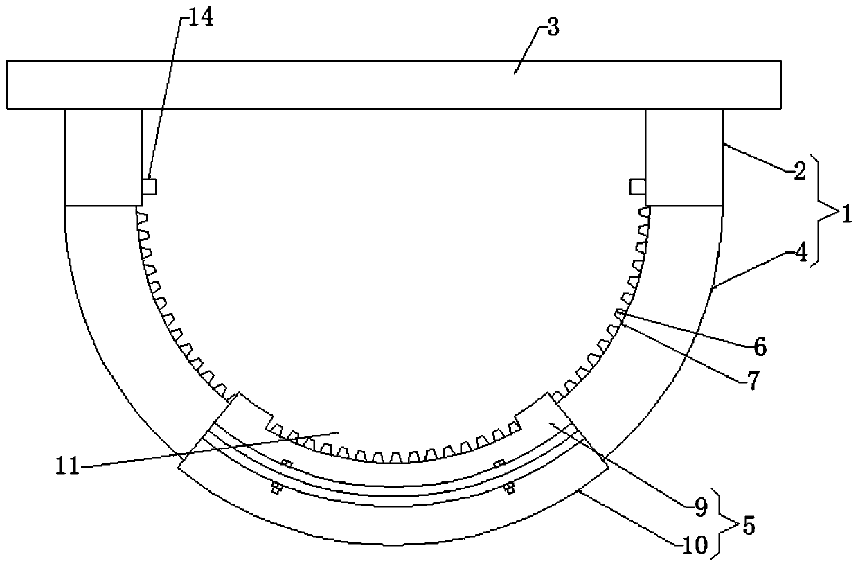
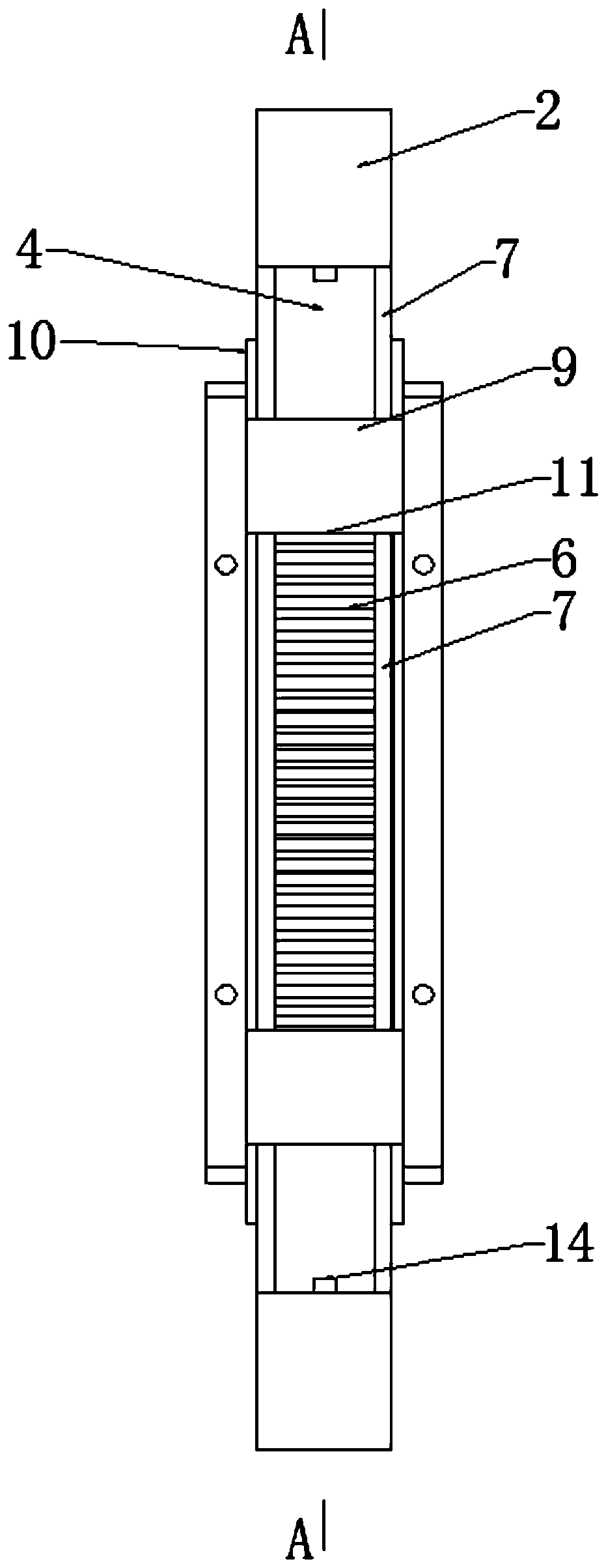
[0029] Such as Figure 1-4 As shown, according to the technical solution provided by the present invention: a pitching mechanism for air traffic control radar antenna, including a fixed frame 1, the fixed part 2 on the fixed frame 1 is fixedly connected with the radar antenna 3, and the arc on the fixed frame 1 A tilting mechanism 5 is sleeved on the curved part 4 of the shape.
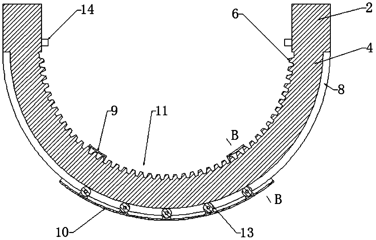
[0030] Protruding teeth 6 are provided on the inner side of the curved portion 4 , and stepped surfaces 7 are symmetrically provided on the inner wall of the curved portion 4 located on both sides of the convex tooth 6 , and limiting grooves 8 are provided on the outer wall of the curved portion 4 .
[0031] The pitching mechanism 5 includes an upper shell 9 and a lower shell 10 with a circular arc structure, so that the pitching mechanism 5 constitutes a detachable structure, which is convenient for later installation, maintenance and replacement. The upper shell 9 and the lower shell 10 pass through...
Embodiment 2
[0035] Such as Figure 5-6 As shown, on the basis of Embodiment 1, the following technical solution can also be adopted: the fixed frame 1 is designed as a complete ring structure, the inner wall of the fixed frame 1 is still provided with convex teeth 6, and only the lower shell of the U-shaped structure is reserved. body 10, and both sides of the top of the lower housing 10 are provided with installation grooves 15, and the positions of the installation grooves 15 and the positioning grooves 16 on both sides of the fixed frame 1 are corresponding, and the inner sides of the installation grooves 15 are provided with a plurality of third rollers 17. The third roller 17 is matched with the positioning groove 16, so that the fixed frame 1 is not easy to tilt and derail during the rotation process. The travel switch 14 is placed on the side close to the connection with the fixed frame 1, so as to avoid the possibility that the adjustment angle is too large and the support frame 1...
PUM
 Abstract
Description
Claims
Application Information