
Inner spinning feeding device for bottom plate of opposite-wheel driving power spinning equipment

A technology of powerful spinning and equipment bottom plate, which is applied in the direction of gear transmission, transmission, mechanical equipment, etc., can solve the problems of poor versatility, long manufacturing cycle, high cost of core mold, etc., achieve high positioning accuracy, improve the state of stress, The effect of small mechanism size

Active Publication Date: 2019-11-22
XI AN JIAOTONG UNIV
View PDF5 Cites 0 Cited by
  • Summary
  • Abstract
  • Description
  • Claims
  • Application Information

AI Technical Summary

Problems solved by technology

[0005] The present invention proposes an internal rotation feeding device for the bottom plate of the counter wheel active powerful spinning equipment, which solves the problems of high mandrel cost, poor versatility and long manufacturing cycle in the bottom plate of the existing mandrel spinning equipment, and breaks through the current The small adjustment range of the internal rotation feed device of the existing wheel spinning technology improves the rigidity of the internal rotation feed device

Method used


Image

  • Inner spinning feeding device for bottom plate of opposite-wheel driving power spinning equipment
  • Inner spinning feeding device for bottom plate of opposite-wheel driving power spinning equipment
  • Inner spinning feeding device for bottom plate of opposite-wheel driving power spinning equipment

Examples


Embodiment approach

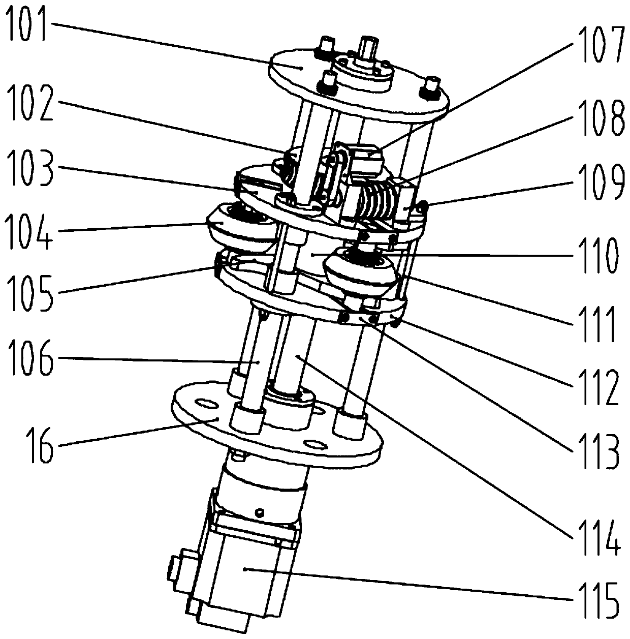
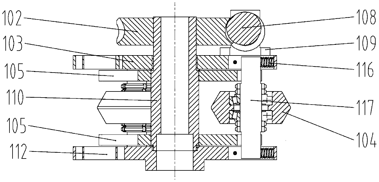
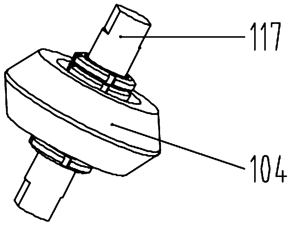
[0037] Implementation method: when the inner wheel 104 is fed radially along the workpiece, the brake motor 107 is used as the power source to drive the worm 108 to rotate through the synchronous pulley, and the worm 108 rotates so that the worm wheel 102 drives the cam installation cylinder 110 to rotate, and the cam installation cylinder 110 The drive cam 105 rotates around the axis, and the convex surface of the cam 105 is tangent to the inner roller shaft 117 so that the inner roller shaft 117 moves outward along the U-shaped grooves on the upper plate 103 of the inner roller and the lower plate 112 of the inner roller to realize radial feed . At the same time, the self-locking function of the worm gear and the brake motor are used to ensure that the inner wheel can be accurately positioned for processing after being radially fed to the specified position.

[0038] During the return journey of the inner turning wheel 104, the reverse rotation of the brake motor 107 first d...


PUM


Abstract

The invention belongs to the technical field of spinning, and relates to an inner spinning feeding device for a bottom plate of opposite-wheel driving power spinning equipment. The inner spinning feeding device comprises an inner spinning roller vertical column, an inner spinning roller top plate, an inner spinning roller upper plate, an inner spinning roller lower plate, a cam, a cam mounting barrel, an inner spinning roller, inner spinning roller shafts, a feed screw, a servo motor and a bottom plate, wherein the inner spinning roller vertical column is perpendicular to the bottom plate, andthe middle section of the inner spinning roller vertical column is connected with the inner spinning roller upper plate and the inner spinning roller lower plate correspondingly through guide sleeves; a plurality of inner spinning roller shafts are arranged between the inner spinning roller upper plate and the inner spinning roller lower plate, the inner spinning roller shafts can slide in U-shaped grooves of the inner spinning roller upper plate and the inner spinning roller lower plate so as to realize radial feeding, the inner spinning roller lower plate is connected with the feeding screwthrough a screw nut, and the servo motor drives the feeding screw rod so as to realize axial feeding. According to the device, a brake motor is used as a power source and is driven by the worm and gear, and the inner spinning roller is driven by the cam to be fed along the radial direction of a workpiece, so that an inner spinning roller mechanism is small in size, large in adjusting range and high in positioning precision.

Description

technical field [0001] The invention belongs to the technical field of spinning processing, and in particular relates to an inner-rotating feeding device for the bottom plate of an active powerful spinning equipment for counter wheels. Background technique [0002] The counter-wheel powerful spinning is developed on the basis of the mandrel spinning, and the inner spinning wheel is used instead of the mandrel to process the inner and outer surfaces of the billet at the same time. [0003] The wheel spinning uses one or several pairs of inner and outer rotating wheels to process the inner and outer sides of the workpiece at the same time. Compared with the traditional spinning method, the inner spinning wheel is used to replace the mandrel, which effectively improves the flexibility of the process, saves the cost of spinning molds, improves the inner surface quality of spinning parts, and overcomes the traditional spinning The disadvantage of different deformation of the inn...

Claims


Application Information

Patent Timeline
IPC IPC(8): B21D22/14
CPCB21D22/14F16H1/166F16H55/02
Inventor 赵升吨李帆朱成成范淑琴蒋红
Owner XI AN JIAOTONG UNIV
Learn More