Mold special for post injection molding sandwich compound insulation building blocks

A composite thermal insulation and post-injection technology, applied in household appliances, other household appliances, applications, etc., can solve the problems of low strength, increased cost, and long cooling and cooling time of polystyrene insulation boards.

Pending Publication Date: 2019-11-22
刘传伟
View PDF0 Cites 1 Cited by
  • Summary
  • Abstract
  • Description
  • Claims
  • Application Information

AI Technical Summary

Problems solved by technology

[0002] After a period of production practice, the existing special mold for forming composite thermal insulation blocks has exposed some prominent structural and technical defects, which are mainly manifested in: 1) The partition plate of the upper mold box is fixed and dead, and the 2) Small round aluminum caps with several air holes are used to inlay the left and right fixed partitions, the upper top plate and the lower bottom plate, which will easily cause air hole blockage and cooling. Water clogging leads to slow temperature rise and long cooling time, resulting in long production cycle and low production efficiency; 3) Due to the clogging temperature of the pores cannot meet the requirements, the strength of the injection-molded polystyrene insulation board is low; 4) It is composed of two blocks. The par

Method used


Image

  • Mold special for post injection molding sandwich compound insulation building blocks
  • Mold special for post injection molding sandwich compound insulation building blocks
  • Mold special for post injection molding sandwich compound insulation building blocks

Examples


Embodiment Construction

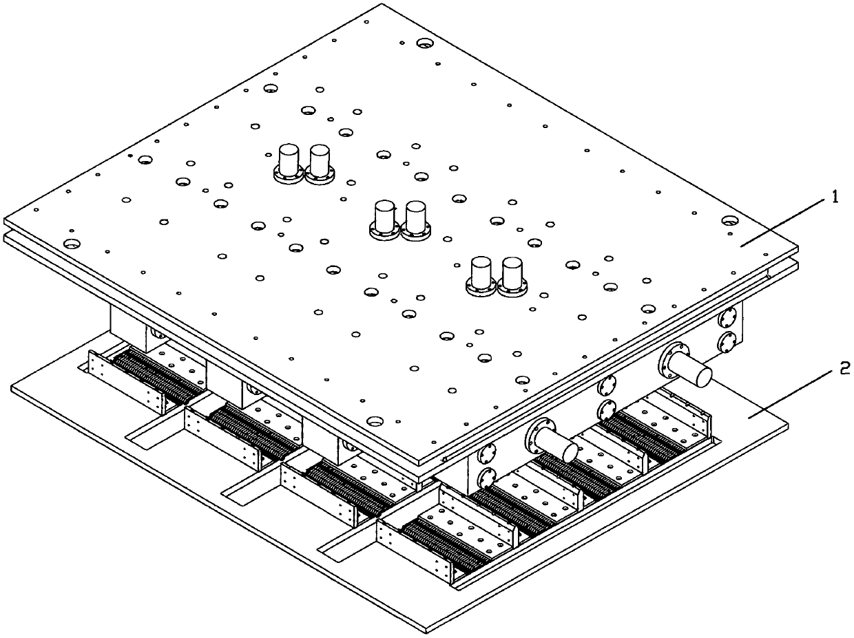
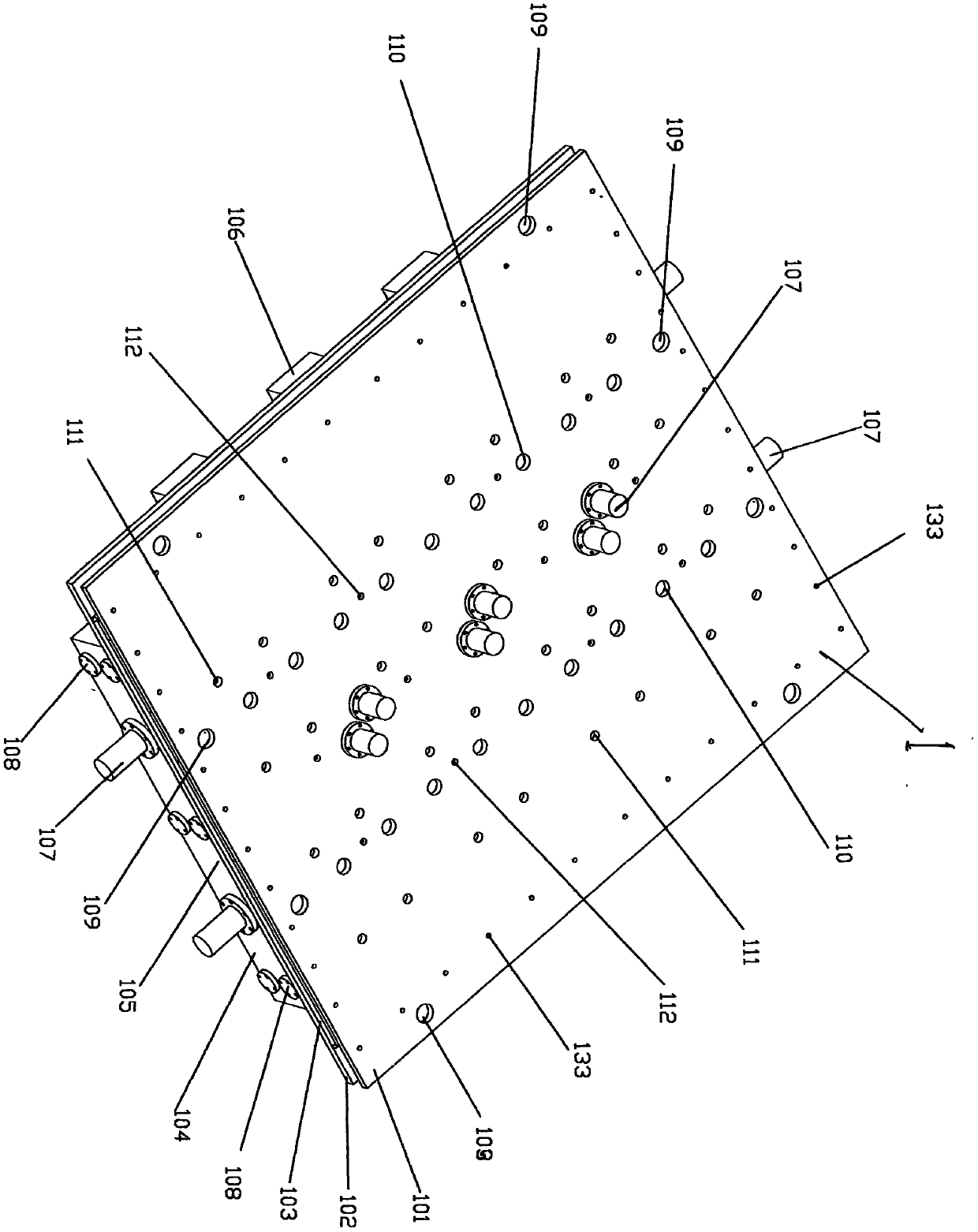
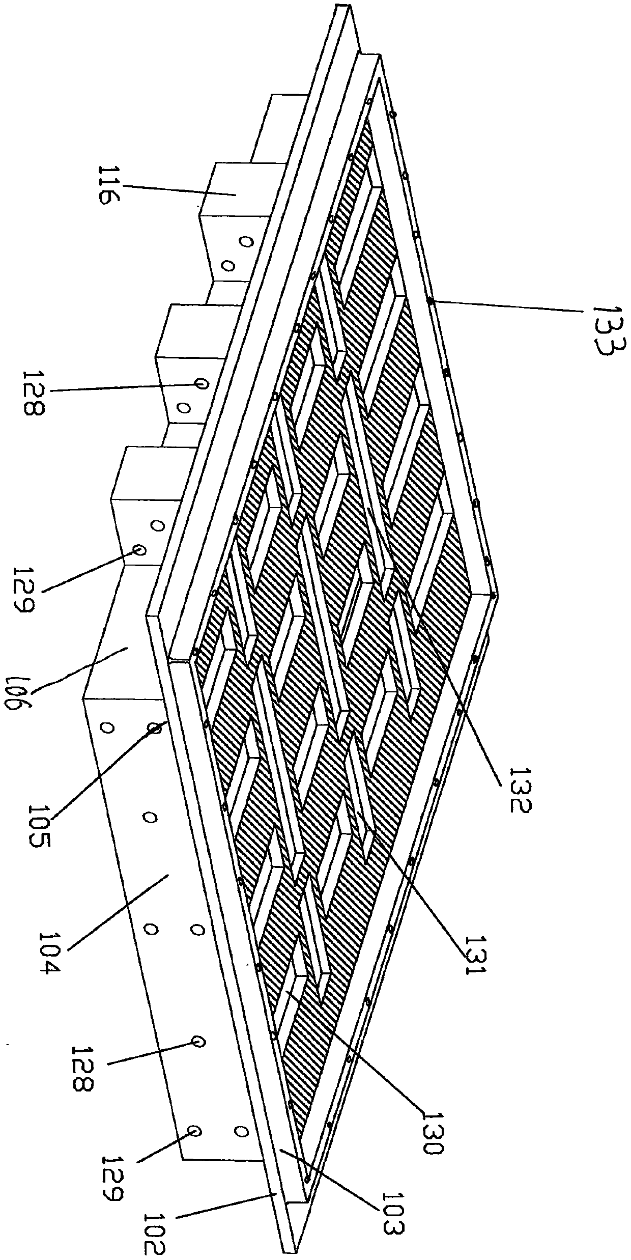
[0079] The present invention is achieved like this, below in conjunction with appendix Figure 1 to Figure 17 For further explanation: a special mold for post-injection sandwich composite thermal insulation blocks, including an upper mold 1 and a lower mold 2; , mold frame 104, several oil cylinders 107, several intermediate clamping plates 113, two end clamping plates 114, several guide shafts 115, several guide shaft flanges 108, several top steam / cooling water passing nets Plate 117, several side vertical steam / cooling water pass through mesh plate 121, several large heat-resistant rubber backing plates 118, several small heat-resistant rubber backing plates 119, and several top partitions 120; the lower mold 2 Consists of the lower template 201, several lower mold inner partitions 202, several lower mold outer partitions 203, several lower mold bottom steam / cooling water passing through the mesh plate 206, several large heat-resistant rubber backing plates 118, several A ...


PUM


Abstract

The invention discloses a mold special for post injection molding sandwich compound insulation building blocks. The mold comprises an upper mold 1 and a lower mold 2, and is characterized in that theupper mold 1 is composed of an upper connecting plate 101, a lower connecting plate 102, a steam/water chamber square frame 103, a mold frame 104, multiple oil cylinders 107, multiple middle clampingplates 113, two end clamping plates 114, multiple guide shafts 115, multiple guide shaft flanges 108, multiple top steam/cooling water passing net plates 117, multiple side face vertical steam/coolingwater passing net plates 121, multiple large heat-resisting rubber base plates 118, multiple small heat-resisting rubber base plates 119 and multiple top partition plates 120; and the lower mold 2 iscomposed of a lower connecting plate 201, multiple lower mold inner partition plates 202, multiple lower mold outer partition plates 203, multiple lower mold bottom steam/cooling water passing net plates 206, multiple large heat-resisting rubber base plates 118, multiple small heat-resisting rubber base plates 119 and a steam/cooling water chamber 210. The mold is novel in design, reasonable in structure, low in manufacturing cost, high in production efficiency and long in service life.

Description

technical field [0001] The invention relates to a special mold for a post-injection sandwich composite thermal insulation block, which belongs to the field of concrete product processing mold technology and mold production. Background technique [0002] After a period of production practice, the existing special mold for forming composite thermal insulation blocks has exposed some outstanding structural and technical defects, which are mainly manifested in: 1) The partition plate of the upper mold box is fixed and dead, and the 2) Small round aluminum caps with several air holes are used to inlay the left and right fixed partitions, upper top plate and lower bottom plate, which will easily cause air hole blockage and cooling. Water clogging leads to slow temperature rise and long cooling time, resulting in long production cycle and low production efficiency; 3) Due to the clogging temperature of the pores cannot meet the requirements, the strength of the injection-molded pol...

Claims


Application Information

Patent Timeline
IPC IPC(8): B29C45/14B29C45/18B29C45/26B29C45/72B29K709/06B29L31/10
CPCB29C45/14008B29C45/14065B29C45/18B29C45/26B29C45/72B29C2045/2683B29K2709/06B29L2031/10
Inventor 刘传伟
Owner 刘传伟
Why Eureka
Try Eureka