Injection strategy for low noise and soot combustion

a low noise and soot combustion technology, applied in the direction of machines/engines, mechanical equipment, electric control, etc., can solve the problems of increasing the formation of soot, excessive engine noise, and undesirable soot particle emissions, and achieve the effect of reducing engine noise and soo

Inactive Publication Date: 2005-10-13
GENERAL MOTORS COMPANY
View PDF4 Cites 25 Cited by
  • Summary
  • Abstract
  • Description
  • Claims
  • Application Information

AI Technical Summary

Benefits of technology

[0007] In the present invention, a new fuel injection method is provided to reduce engine noi...

Problems solved by technology

Fuel injection timing and ignition lag with high rates of pressure rise can cause excessive engine noise while advanced ignition and burning of unvaporized fuel droplets will increase the formation of soo...

Method used


Image

  • Injection strategy for low noise and soot combustion
  • Injection strategy for low noise and soot combustion
  • Injection strategy for low noise and soot combustion

Examples


Embodiment Construction

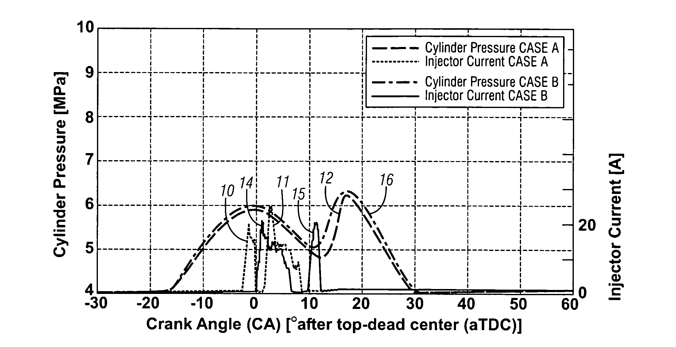
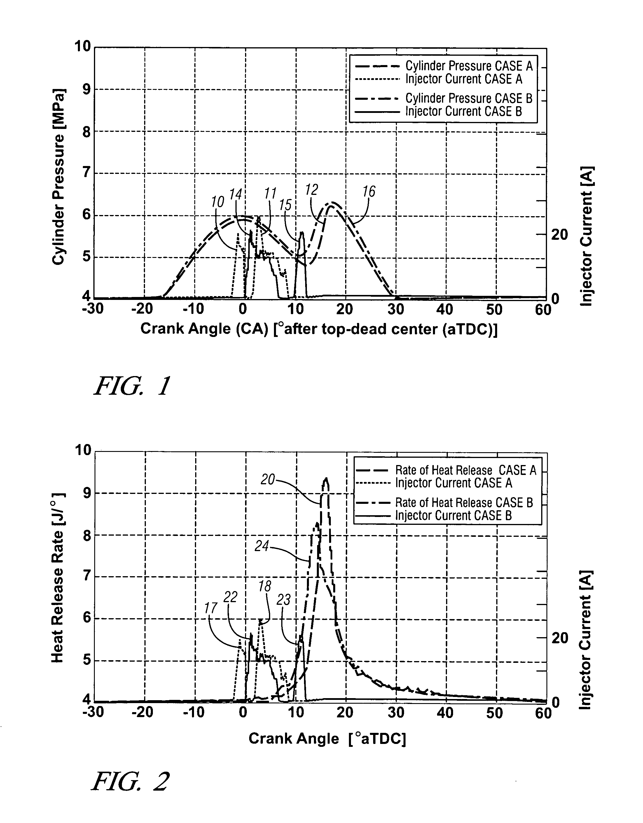
[0015] The present invention, provides a novel strategy or method by injecting fuel in two distinct fuel injection events per engine cycle. The first injection event is main fuel injection, which occurs when the crankshaft is near top-dead center. The main injection event delivers a majority of the fuel needed to provide a majority of the power produced during combustion.

[0016] The second injection event is post injection, which occurs shortly after the main fuel injection event. The post injection event provides a supplemental amount of fuel to the combustion chamber to reduce the rate of pressure rise while increasing, turbulence, mixing and cylinder pressure within the combustion chamber.

[0017] In operation, intake air drawn in and compressed by a piston within each combustion chamber. As the piston nears top dead center, and the crankshaft angle approaches 0 degrees, an ECM actuates the fuel injector to initiate the main fuel injection event which injects between 80 and 95% of...


PUM


Abstract

The present invention, provides a strategy or method for injecting fuel in two distinct fuel injection events per engine cycle. The first injection event is main fuel injection, which occurs when the crankshaft is near top-dead center. The main injection event delivers a majority of the fuel needed to provide a majority of the power produced during combustion. The second injection event is post injection, which occurs shortly after the main fuel injection event. The post injection event provides a supplemental amount of fuel to the combustion chamber to reduce the rate of pressure rise while increasing, turbulence, mixing and cylinder pressure within the combustion chamber to reduce the formation of soot. In addition, the combination of the main fuel injection event and the post fuel injection event reduces engine noise by reducing heat release rates and the rate of combustion chamber pressurization.

Description

CROSS-REFERENCE TO RELATED APPLICATIONS [0001] This application claims priority from U.S. Provisional Patent Application No. 60 / 560,455 filed Apr. 8, 2004.TECHNICAL FIELD [0002] This invention relates to diesel fuel injection methods and, more particularly, to a method of delivering multiple fuel injections into a combustion chamber to minimize engine noise and soot. BACKGROUND OF THE INVENTION [0003] A four-stroke diesel engine cycle conventionally includes intake, compression, expansion and exhaust strokes. Intake air drawn into a combustion chamber on the intake stroke is compressed during the subsequent compression stroke. Fuel is then injected into the combustion chamber and ignited by the hot compressed gases. Burning of the fuel within the combustion chamber generates heat and pressure, which produces power on the expansion stroke. Combustion products are exhausted during the exhaust stroke. Fuel injection timing and ignition lag with high rates of pressure rise can cause exc...

Claims


Application Information

Patent Timeline
IPC IPC(8): F02B17/00F02B31/00F02D41/40F02M45/04
CPCF02D41/405F02M45/04Y02T10/44Y02T10/40
Inventor STOJKOVIC, BORIS D.JEHLIK, FORREST A.TAHRY, SHERIF H. ELKRIEGER, ROGER B.
Owner GENERAL MOTORS COMPANY
Why Eureka
Try Eureka