Supercharge Your Innovation With Domain-Expert AI Agents!

A-pillar dynamic visual system

A dynamic, rear-view mirror technology, applied in vehicle components, optical observation devices, signaling devices, etc., can solve problems such as scene overlap, new blind spots, and inability to adjust blind spot images.

Pending Publication Date: 2019-11-22
贾实
View PDF6 Cites 7 Cited by
  • Summary
  • Abstract
  • Description
  • Claims
  • Application Information

AI Technical Summary

Problems solved by technology

[0003] At present, there is a dilemma in the size of the cross-sectional area of ​​the A-pillar. If it is too small, it will lead to insufficient strength of the vehicle body. If it is too large, it will affect the driver's vision.
The existing technology uses the cameras on the left and right rearview mirrors to form a fixed field of view image, which is displayed on the two display screens inside the A-pillar to connect with the external environment to solve the problem of the blind area of ​​the A-pillar. Factors such as the front and rear adjustment of the seat and the change of the viewing angle position will cause the collected image to overlap with the real scene, and the blind spot image cannot be adjusted in real time according to the horizontal position of the human eye and the steering angle of the head, and a new blind spot will be generated, artificially causing hidden dangers to driving safety , in order to solve the above problems, we propose A-pillar dynamic visual system

Method used


Image

  • A-pillar dynamic visual system
  • A-pillar dynamic visual system

Examples


Embodiment Construction

[0018] The following will clearly and completely describe the technical solutions in the embodiments of the present invention with reference to the accompanying drawings in the embodiments of the present invention. Obviously, the described embodiments are only some, not all, embodiments of the present invention. Based on the embodiments of the present invention, all other embodiments obtained by persons of ordinary skill in the art without making creative efforts belong to the protection scope of the present invention.

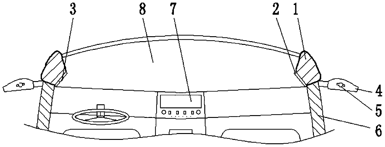
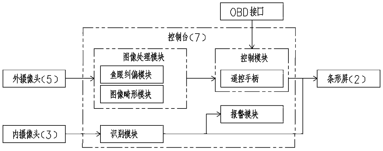
[0019] see figure 1 , figure 2 , the present invention provides a technical solution: A-pillar dynamic visual system, including A-pillar 1, a shell 8 is fixedly installed between the A-pillars 1, a console 7 is embedded in the lower surface of the shell 8, and the left A-pillar The inner camera 3 is fixedly installed on the inner side of 1, and the inner camera 3 is located on the front side of the housing 8. The inner side of the A-pillar 1 is fixedly insta...


PUM

PropertyMeasurementUnit
Field of viewaaaaaaaaaa

Abstract

The invention discloses an A-pillar dynamic visual systempillar. The system includes A pillars, a shell is fixedly mounted between the pillars A; a console is embedded in the lower surface of the shell; an inner camera is fixedly mounted on the inner side of the left pillar A; a strip-shaped screen is fixedly mounted on the inner side of the pillar A; a vehicle door is rotationally mounted on thelower side of the pillar A; a rearview mirror is fixedly mounted on the outer side of the vehicle door; an outer camera is fixedly installed at the rear end of the rearview mirror, the console comprises a recognition module, an image processing module, a control module and an alarm module, the inner camera is used for shooting the face of a driver, obtaining the eye level and the head steering confidence and transmitting the eye level and the head steering confidence to the recognition module, and the recognition module adjusts blind area images displayed by the strip-shaped screen in real time according to recognized information. Compared with the prior art, the device can monitor the horizontal position and the head turning angle of human eyes in real time, and corresponding blind area images collected by the outer camera are displayed on the strip-shaped screen on the inner side of the pillar A and form a blind-area-free overall image with a real scene.

Description

technical field [0001] The invention relates to the technical field of automobile safety, in particular to an A-pillar dynamic visual system. Background technique [0002] The A-pillar blind area refers to the blind area of ​​vision when the car is driving. Generally, there are three columns on each side of the body of a car, and the slanted columns on both sides of the front windshield are called A-pillars. Whenever the car turns or enters a curve, the driver's field of vision will be partially blocked by the A-pillars, resulting in a visual field. on the blind spot. [0003] At present, there is a dilemma in the size of the cross-sectional area of ​​the A-pillar. If it is too small, it will lead to insufficient strength of the body, and if it is too large, it will affect the driver's vision. The existing technology uses the cameras on the left and right rearview mirrors to form a fixed field of view image, which is displayed on the two display screens inside the A-pillar...

Claims


Application Information

Patent Timeline
IPC IPC(8): B60R1/00B60Q9/00
CPCB60R1/00B60Q9/00B60R2300/105B60R2300/30B60R2300/304B60R2300/802
Inventor 贾实
Owner 贾实
Features
  • R&D
  • Intellectual Property
  • Life Sciences
  • Materials
  • Tech Scout
  • Unparalleled Data Quality
  • Higher Quality Content
  • 60% Fewer Hallucinations
Learn More