Steel wire rope winding and unwinding reel for hauling ship in ocean

A technology for wire rope, rewinding and unwinding, which is applied to the field of wire rope rewinding and unwinding of marine tugboats, can solve the problems of inconvenient disassembly of wire rope rewinding and unwinding, and achieves a high endurance, flexibility and high working performance. Effect

CN110482331AInactive Publication Date: 2019-11-22TANGSHAN HARBIN SHIP TECH CO LTD
0 Cites 1 Cited by

Patent Information

Authority / Receiving Office
CN · China
Patent Type
Applications(China)
Current Assignee / Owner
Publication Date
2019-11-22
Estimated Expiration
Not applicable · inactive patent

Smart Images

  • Figure 1
    Figure 1
  • Figure 2
    Figure 2
  • Figure 3
    Figure 3
Patent Text Reader

Abstract

The invention discloses a steel wire rope winding and unwinding reel for hauling a ship in the ocean. In order to solve the problem that an existing steel wire rope winding and unwinding reel is inconvenient in removal, the following scheme is provided; the steel wire rope winding and unwinding reel comprises two bases arranged symmetrically, and a connecting seat arranged horizontally is installed between the two bases; the connecting seat is located above the bases, and two limiting blocks arranged vertically are welded on the tops of the opposite ends of the two bases; the both sides of theconnecting seat are provided with sliding chutes formed horizontally, and the limiting blocks are slidably arranged in the sliding chutes in a sleeving mode; and support plates arranged vertically are welded at one ends, far away from the connecting seat, of the two bases, and a biaxial motor arranged horizontally is welded on the top of the connecting seat. The steel wire rope winding and unwinding reel is rational in structure, and can be used for hauling the ship effectively; components on the steel wire rope winding and unwinding reel can be removed simply and conveniently, and the heightof the steel wire rope winding and unwinding reel can be regulated flexibly; the steel wire rope winding and unwinding reel is high in working performance, convenient in use, and suitable for promotion.
Need to check novelty before this filing date? Find Prior Art

Description

technical field

[0001] The invention relates to the technical field of wire rope rewinding and unwinding, in particular to a wire rope rewinding and unwinding of an ocean tugboat. Background technique

[0002] The steel wire rope is a spiral steel wire bundle that twists the steel wires that meet the requirements of mechanical properties and geometric dimensions according to certain rules. The steel wire rope is composed of steel wire, rope core and grease.

[0003] Most of the existing marine tugboats are equipped with corresponding wire rope retractable and unwinding coils, and the steel wire rope is used to drag the ship through the wire rope retracting and unwinding coil. In the process, most of them are set up together with the ocean tugboat. When the wire rope rewinding and unwinding needs to be overhauled and maintained after a long period of use, it is difficult for the user to easily and conveniently adjust the ocean The wire rope rewinding and unwinding coils on t...

Examples

Embodiment Construction

[0021] The following will clearly and completely describe the technical solutions in the embodiments of the present invention with reference to the accompanying drawings in the embodiments of the present invention. Obviously, the described embodiments are only some, not all, embodiments of the present invention.

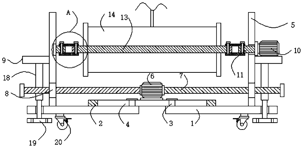
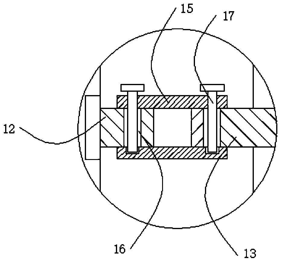
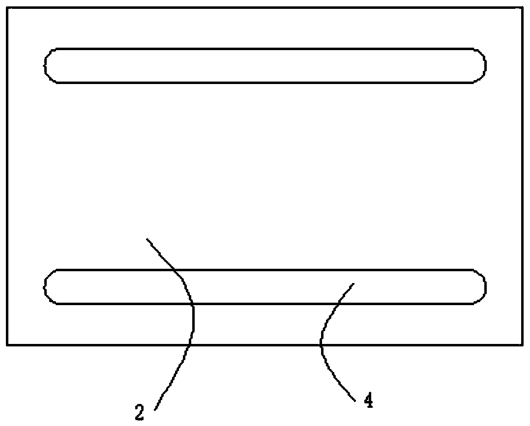
[0022] See attached Figure 1-3 , a kind of wire rope rewinding and unwinding of a marine tugboat, comprising two symmetrically arranged bases 1, a connecting seat 2 arranged horizontally between the two bases 1, the connecting seat 2 is located above the base 1, and the two bases 1 The top of the opposite end is welded with two vertically arranged limit blocks 3, and the two sides of the connecting seat 2 are provided with horizontally arranged chute 4, and the limit block 3 is slidably set inside the chute 4, and the two bases 1 The end far away from the connecting seat 2 is welded with a vertically arranged support plate 5, and the top of the connecting seat 2 is ...