Tower crane multimachine anti-collision device
A technology of anti-collision devices and tower cranes, which is applied to cranes, supporting machines, mechanical equipment, etc., can solve the problems of not being able to collect the swing arm body of tower cranes in all directions, easy to miss, and cannot be installed, so as to achieve remote data sharing , to ensure stability and reliability, to ensure the effect of accuracy and comprehensiveness
- Summary
- Abstract
- Description
- Claims
- Application Information
AI Technical Summary
Problems solved by technology
Method used
Image
Examples
Embodiment 1
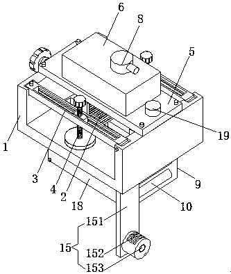
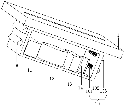
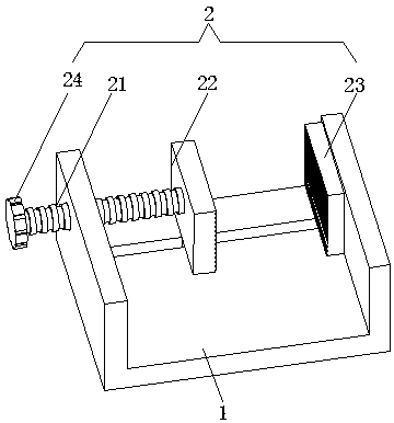
[0027]A multi-machine anti-collision device for tower cranes, comprising a U-shaped mounting plate 1, a fixing mechanism 2, a folding mechanism 3, an angle adjustment mechanism 7, and a bottom anti-collision mechanism 15; the U-shaped mounting plate 1 is a stainless steel U-shaped mounting plate, and the U-shaped Mounting plate 1 provides installation and connection. The middle part of the upper end of U-shaped mounting plate 1 is connected to base plate 5 through bolts. Base plate 5 provides support connection. The upper end of base plate 5 is provided with adjustment box 6, which provides installation space. U-shaped mounting plate The bottom end of 1 is provided with a control box 9, the front end of the control box 9 is an opening mechanism, the front end of the control box 9 is connected with the box cover 18 by bolts, and the control box 9 provides installation space; the fixing mechanism 2 is arranged on the U-shaped mounting plate 1 Inside, the fixing mechanism 2 includ...
Embodiment 2
[0032] This embodiment differs from Embodiment 1 in that it also includes a reinforcement mechanism 4 and a heat dissipation and rainproof mechanism 10. The reinforcement mechanism 4 is arranged inside the folding mechanism 3. Knob 43, pressing screw rod 41 is threadedly connected with support block 33, and circular pressing plate 42 is arranged on the bottom end of pressing screw rod 41, and adjusting knob 43 is arranged on the top of pressing screw rod 41, and turning adjustment knob 43, because applying pressure screw rod 41 is threadedly connected with the support block 33, and the circular pressure plate 42 tightly presses the swing arm rod body of the tower crane to realize side clamping and reinforcement to ensure the overall stability and reliability of the device; the heat dissipation and rainproof mechanisms 10 are respectively arranged on the left and right sides of the control box 9 On the box wall, the heat dissipation and rainproof mechanism 10 includes a strip-sh...
Embodiment 3
[0034] This embodiment differs from Embodiment 1 in that it also includes a rotating shaft 16 and an angle sensor 17, the rotating shaft 16 rotates with the rotation of the driving gear 72, the angle sensor 17 detects the number of rotations, and the rotating shaft 16 is arranged on the driving gear 72 The upper end center of the angle sensor 17 is arranged on the inner top wall of the adjustment box 6, the rotating shaft of the angle sensor 17 is fixedly connected with the upper end of the rotating shaft 16, and the angle sensor 17 is electrically connected with the PLC controller 12.
[0035] When in use: attach the U-shaped mounting plate 1 to the outside of the end of the swing arm rod body of the tower crane, and turn the knob 24. Since the fixing screw 21 is threadedly connected with the middle part of the left wall of the U-shaped mounting plate 1, the fixing screw 21 is connected to the middle of the left wall of the U-shaped mounting plate 1 The fixed splint 22 is conn...
PUM
 Abstract
Description
Claims
Application Information
 - R&D
- Intellectual Property
- Life Sciences
- Materials
- Tech Scout
- Unparalleled Data Quality
- Higher Quality Content
- 60% Fewer Hallucinations
Browse by: Latest US Patents, China's latest patents, Technical Efficacy Thesaurus, Application Domain, Technology Topic, Popular Technical Reports.
© 2025 PatSnap. All rights reserved.Legal|Privacy policy|Modern Slavery Act Transparency Statement|Sitemap|About US| Contact US: help@patsnap.com


